
Touch-type variable resistor structure

a resistor and variable technology, applied in the direction of resistor terminals/electrodes, resistors adjusted by mechanical pressure/force, resistors adjusted by short-circuiting resistive elements, etc., can solve the problem of limited operation sensitivity, and achieve the effect of reducing space occupation and limited operation sensitivity

Active Publication Date: 2016-12-06
TAIWAN ALPHA ELECTRONICS
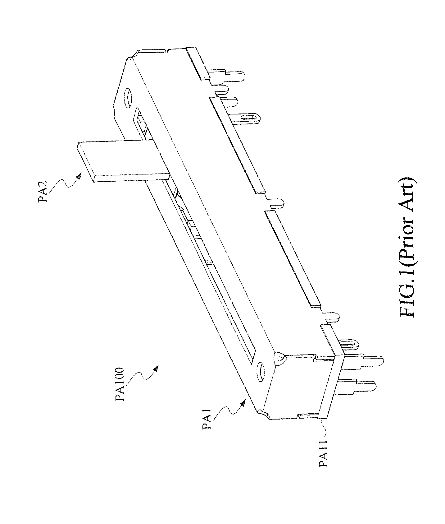
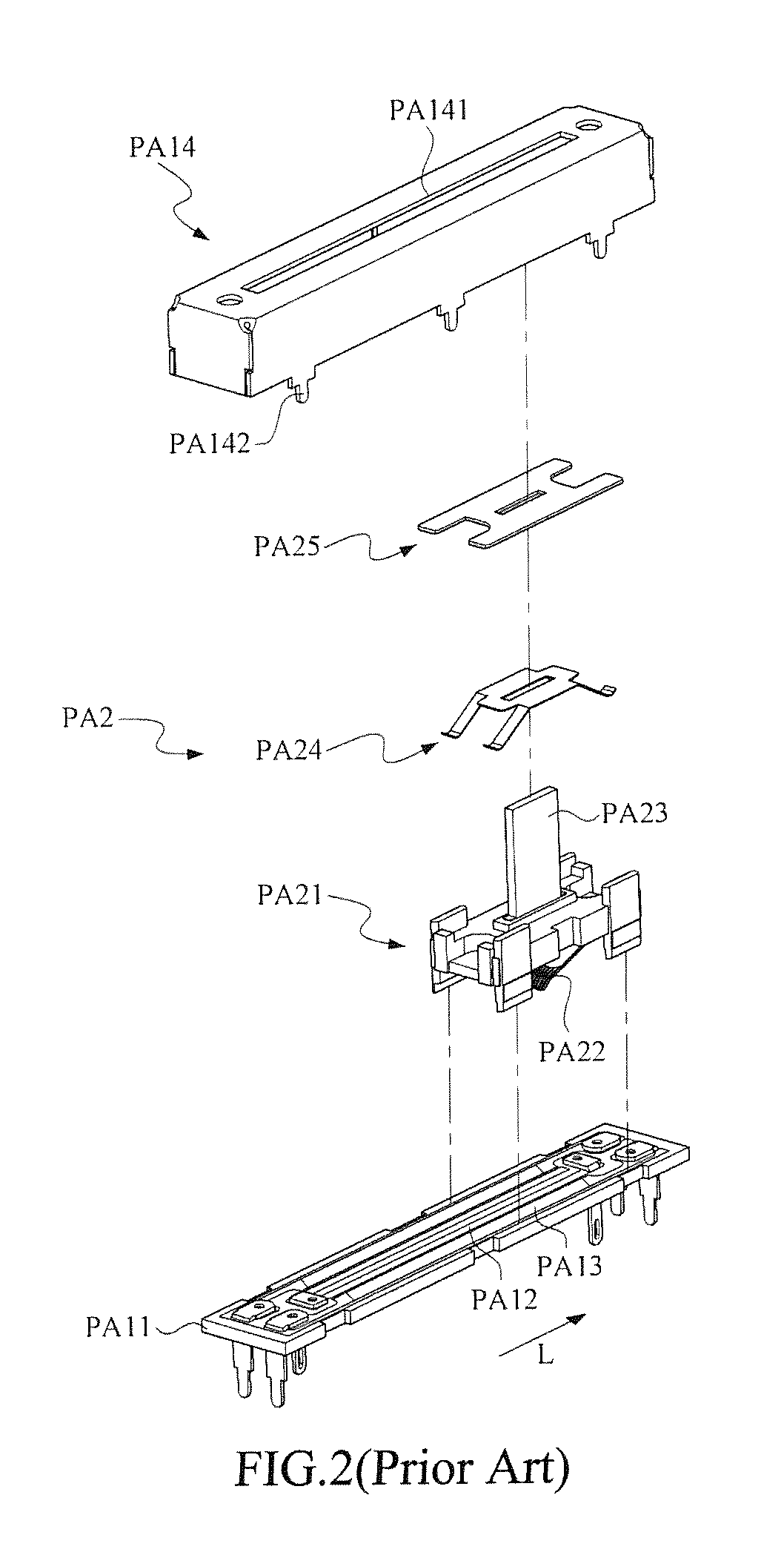
View PDF8 Cites 3 Cited by
  • Summary
  • Abstract
  • Description
  • Claims
  • Application Information

AI Technical Summary

Benefits of technology

[0013]As stated above, in the art, the conventional variable resistor would inevitably occupy a substantial room, and the operational sensitivity is limited. In addition, since the conventional variable resistor can only provide single mode usage for the user to generate a single output signal, so, accordingly, it is the primary object of the present invention to provide a touch-type variable resistor structure that can reduce the space occupation effectively, provide the user a more sensitive operational performance, and perform a dual touch-mode operation upon the flexible-touch base plate for producing simultaneously two sets of output signals.
[0016]In the present invention, the touch-type variable resistor structure can provide the user to connect the electricity-conductive layer and the two resistance layers by depressing the flexible-touch base plate. Since the positive end and the negative end of the two resistance layers are reversely arranged, thus two voltage differences would be generated while a single-point depression upon the flexible-touch base plate is performed to couple electrically the electricity-conductive layer and the two resistance layers simultaneously. Hence, a mono or single touch-mode operation of the present invention is complete.
[0023]In the present invention, the touch-type variable resistor structure can provide the user to electrically connect the electricity-conductive layer and the detection circuit layers by simply depressing the flexible-touch base plate. Since the positive end and the negative end of the two resistance layers are reversely arranged, thus two voltage differences would be generated while a single-point depression upon the flexible-touch base plate is performed to couple electrically the electricity-conductive layer and the two resistance layers simultaneously. In addition, while a dual touch-mode operation is performed upon the flexible-touch base plate, two different current paths for the two resistance layers would be formed so as to produce two different voltage differences. In addition, with the help of the arrangement of the detection circuit layer along the extension direction, the effective area for depressing the flexible-touch base plate can be enlarged. Namely, the effective area of the depression is mainly dependent to the length of the detection circuit layer and the corresponding arrangement, and so the present invention can successfully enhance the control convenience to various users.

Problems solved by technology

As stated above, in the art, the conventional variable resistor would inevitably occupy a substantial room, and the operational sensitivity is limited.

Method used


Image

  • Touch-type variable resistor structure
  • Touch-type variable resistor structure
  • Touch-type variable resistor structure

Examples


first embodiment

[0056]Refer now to FIG. 5, FIG. 6 and FIG. 7; in which FIG. 6 demonstrates a single-finger touch upon the aforesaid first embodiment of the touch-type variable resistor structure of FIG. 5, and FIG. 7 demonstrates a schematic view of the circuitry related to FIG. 6.

[0057]As shown, the first positive terminal 141 and the first negative terminal 142 are both electrically coupled to a power source 200a, while the second positive terminal 151 and the second negative terminal 152 are electrically coupled to another power source 200b. A first voltage detection element V1 is located between the electrode contact point 221 and the first positive terminal 141, and a second voltage detection element V2 is located between the electrode contact point 221 and the second positive terminal 151. In this embodiment, the output voltages for the power source 200a and the power source 200b are the same. However, in some other embodiments, the positive end of one power sources can be connected to both t...

second embodiment

[0065]Refer now to FIG. 11 and FIG. 12; in which FIG. 11 is a schematic exploded view of the touch-type variable resistor structure in accordance with the present invention, and FIG. 12 is another view of FIG. 11.

[0066]As shown, the touch-type variable resistor structure 100′ includes a resistor-base plate 1′, a conductive base plate 2′ and a separator member 3′.

[0067]The resistor-base plate 1′ includes a main plate body 11′, two first resistance layer 12a and 12b, a plurality of first detection circuit layers 13a and 13b, a first electrode set 14′ and a second electrode set 15′. The main plate body 11′ has a touch portion 111′ and a wiring portion 112′, in which the wiring portion 112′ is extended along a extension direction L2 from the touch portion 111′.

[0068]The first resistance layers 12a and the second resistance layers 12b are arranged in a predetermined interval manner on the touch portion 111′ of the main plate body 11′, and are all extended along the extension direction L2...


PUM


Abstract

A touch-type variable resistor structure includes a resistor-base plate, a conductive base plate and a separator member. The resistor-base plate further includes a main plate body and a resistance layer. The resistance layer extended along an extension direction is located on the main plate body. The conductive base plate located on the resistor-base plate includes an electricity-conductive layer facing the resistor-base plate. The separator member located between the resistor-base plate and the conductive base plate further has a central opening. One of the main plate body and the main conductive plate body is formed as a flexible-touch base plate. While the flexible-touch base plate is depressed, part of the electricity-conductive layer would pass through the central opening to electrically couple the resistance layer.

Description

[0001]This application claims the benefit of Taiwan Patent Application Serial No. 104202926, filed Feb. 25, 2015, the subject matter of which is incorporated herein by reference.BACKGROUND OF INVENTION[0002]1. Field of the Invention[0003]The invention relates to a touch-type variable resistor structure, and more particularly to a touch-type resistor structure that utilizes a depression operation to electrically couple an electricity-conductive layer to a resistance layer through a central opening of a separator member.[0004]2. Description of the Prior Art[0005]Generally speaking, current variable resistor related apparatus is mainly consisted of a circuit board having a resistance layer and a resistance-adjusting assembly having a conductive brush, such that a user can adjust the signal output pattern by varying the contact position between the conductive brush and the resistance layer, such that an option to vary the resistance by sliding the resistance-adjusting assembly can be pr...

Claims


Application Information

Patent Timeline
Patent Type & Authority Patents(United States)
IPC IPC(8): H01C10/12H01C10/10H01C1/14
CPCH01C10/10H01C1/14H01C10/06
Inventor HUANG, TZU-HSUANLIU, WEI-LIANGTSAI, HSIN-TSUN
Owner TAIWAN ALPHA ELECTRONICS
Learn More