Shape memory actuator with multistable driven element

a memory actuator and actuator technology, applied in the direction of machines/engines, valve details, valve arrangements, etc., can solve the problems of unsuitable scaling down in size, unreliability, and bulky and expensive types of known sma actuators, so as to minimize and the effect of minimizing the cost and bulkiness of the actuator

Active Publication Date: 2016-12-06
SAES GETTERS SPA
View PDF15 Cites 2 Cited by
  • Summary
  • Abstract
  • Description
  • Claims
  • Application Information

AI Technical Summary

Benefits of technology

The actuator described in this patent has several advantages. First, it can move between different positions without needing extra power, which means the SMA wire can be made smaller and cheaper. Second, it can use a single wire, instead of two, which makes it more cost-effective. Third, it has a longer lifespan because it's only activated every other time. Lastly, because it's simple and durable, it can be used in harsh environments.

Problems solved by technology

All these prior art documents disclose actuators that are quite complicated, bulky and rather expensive, usually involving the use of two SMA wires and / or mechanical stabilization elements such as a diaphragm for moving the shutter between the two (or more) stable positions.
These types of known SMA actuators are therefore unsuitable to be scaled down in size and not fully reliable when used in harsh environments due their rather delicate and sophisticated operation.

Method used


Image

  • Shape memory actuator with multistable driven element
  • Shape memory actuator with multistable driven element
  • Shape memory actuator with multistable driven element

Examples


second embodiment

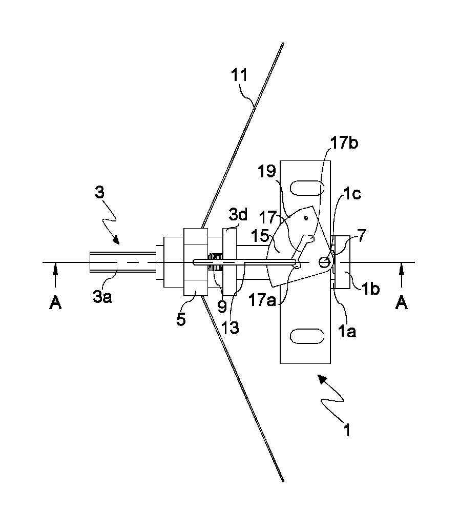
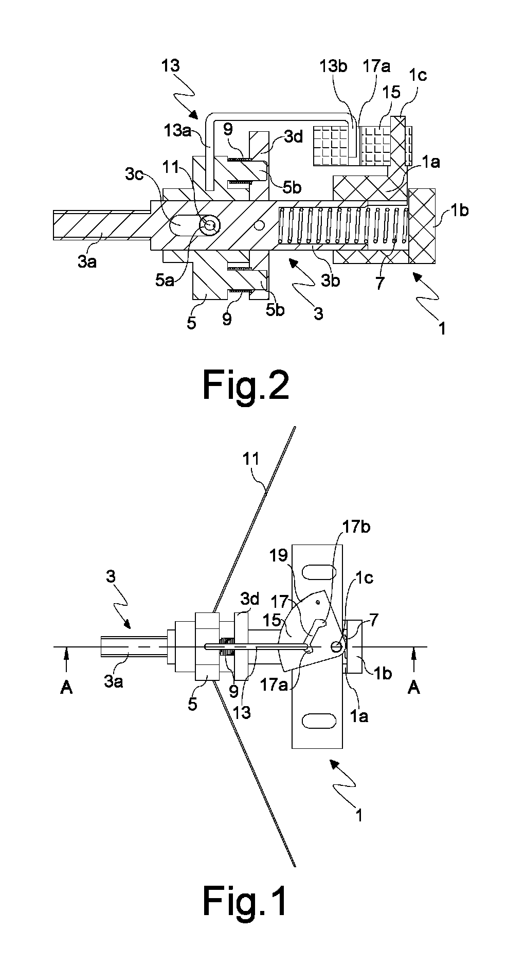
[0042]FIG. 9 shows the actuator that differs from the above-described actuator only in the type of engaging means arranged on disk 3d and rotating member 15, namely mechanical means rather than magnetic means. More specifically, a first substantially L-shaped engagement member 21a is provided on disk 3d and a second substantially L-shaped engagement member 21b is provided on the rotating member 15. Said two members 21a, 21b are both arranged in the horizontal plane with their internal sides (i.e. the “concave” sides) facing each other so as to achieve the hooking illustrated in FIG. 9, however it is clear that a suitable engagement could be achieved also with different orientations of members 21a, 21b (even in perpendicular planes) as long as their internal sides face each other.

[0043]The actuator operation described above clearly shows how the present actuator achieves the previously mentioned advantages of moving the driven element between two stable positions by activating a sing...

first embodiment

[0046]In both cases the control system for engaging and releasing the magnetic engagement is just the control unit that controls the polarization of the reversible magnet, since the mere reversal of the latter is sufficient to achieve the engagement and disengagement. This also implies that the SMA wire need not be activated to move the magnetic means out of engagement as in the first embodiment illustrated above, whereby bridge 13 and rotating member 15 could even be dispensed with.

[0047]Another kind of modification that can be made is aimed at providing more than one operative position, e.g. if the actuator is used on a valve with multiple opening degrees or multiple outlets. In this case a different amount of current is supplied to the SMA wire depending on the position to be reached and therefore on the required degree of contraction of the SMA wire and, correspondingly, engaging means are provided at each of the multiple operative positions. If the stroke required to reach all ...


PUM


Abstract

A shape memory actuator is described. The shape memory actuator has a supporting body, a driven element slidably mounted on the supporting body for movement between a stable rest position and a stable operative position, a driving element that drives the driven element, the movement of the driving element being determined by a SMA wire and by first resilient return means acting to return the driving element to the rest position upon deactivation of the SMA wire, second resilient return means acting on the driven element in opposition to the SMA wire, engaging means suitable to achieve at the operative position a reversible engagement between the driven element and the supporting body, either directly or indirectly, said engagement being able to resist the action of second resilient return means, and a control system for the engagement and disengagement of the engaging means.

Description

CROSS REFERENCE TO RELATED APPLICATIONS[0001]The present application is the U.S. National Stage of International Patent Application PCT / IB2014 / 060037 filed on Mar. 21, 2014 which, in turn, claims priority to Italian Application No. MI2013A000512 filed on Apr. 5, 2013, which is incorporated herein by reference in its entirety.BACKGROUND OF THE INVENTION[0002]The present invention relates to shape memory actuators, i.e. actuators in which the actuating member consists of an element (for example a wire element) made from a shape memory alloy (indicated in the following as “SMA”), and in particular to an actuator in which the driven element is multistable, preferably bistable, i.e. it is moved by a driving element between at least two stable positions. Although specific reference is made in the following to the use of a wire as actuating member, it should be noted that what is being said also applies to other similar elongated shapes, i.e. with a dimension much greater than the other tw...

Claims


Application Information

Patent Timeline
Patent Type & Authority Patents(United States)
IPC IPC(8): F03G7/06F16K31/02F16K31/44
CPCF03G7/065F16K31/025F16K31/44
Inventor ALACQUA, STEFANOBUTERA, FRANCESCOMAZZONI, MATTEO
Owner SAES GETTERS SPA
Why Eureka
Try Eureka