Re-centering a view of a scene of a three-dimensional image of anatomy of interest and an alignment object based on a new location of the alignment object in the three-dimensional image

a three-dimensional image and alignment object technology, applied in image enhancement, image analysis, instruments, etc., can solve the problems of confusing the user's jump from the first view directly to the second view, and it is difficult to understand the relationship between the two views immediately, so as to achieve the effect of smooth transition, efficient manipulation of view parameter values, and better understanding of interaction

Active Publication Date: 2016-11-29
KONINKLIJKE PHILIPS ELECTRONICS NV
View PDF12 Cites 0 Cited by
  • Summary
  • Abstract
  • Description
  • Claims
  • Application Information

AI Technical Summary

Benefits of technology

[0012]The first view in accordance with the first view parameter value corresponds to the first object parameter value, whereas the second view in accordance with the second view parameter value corresponds to the second object parameter value. Jumping from the first view directly to the second view may be confusing for a user. It may be difficult to understand immediately the relationship between the two views, because the two views have been created using a different view parameter value. The sequential visualization of the intermediate view may provide for a smoother transition from the first view to the second view. It may allow the user to better understand the interaction between the object parameter and the view parameter. Consequently, the user can more efficiently manipulate the view parameter value. This can be used for efficiently creating a desirable view of the image.

Problems solved by technology

Jumping from the first view directly to the second view may be confusing for a user.
It may be difficult to understand immediately the relationship between the two views, because the two views have been created using a different view parameter value.

Method used


Image

  • Re-centering a view of a scene of a three-dimensional image of anatomy of interest and an alignment object based on a new location of the alignment object in the three-dimensional image
  • Re-centering a view of a scene of a three-dimensional image of anatomy of interest and an alignment object based on a new location of the alignment object in the three-dimensional image
  • Re-centering a view of a scene of a three-dimensional image of anatomy of interest and an alignment object based on a new location of the alignment object in the three-dimensional image

Examples


Embodiment Construction

[0037]In the following, several embodiments will be described in detail. These embodiments are examples only. The skilled person will appreciate that variations of the described embodiments are possible within the scope of the claims.

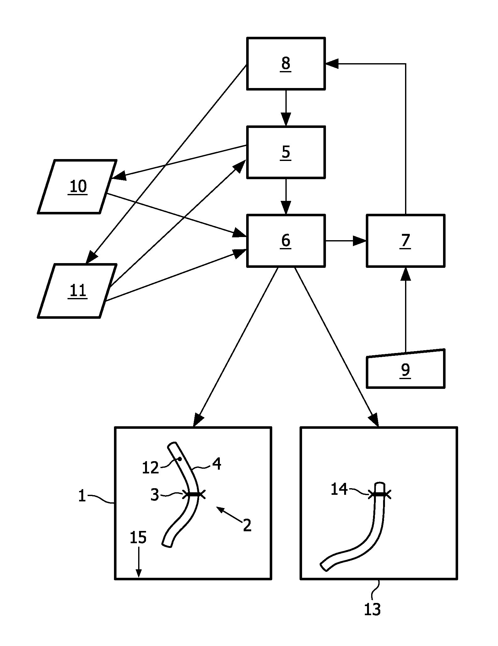
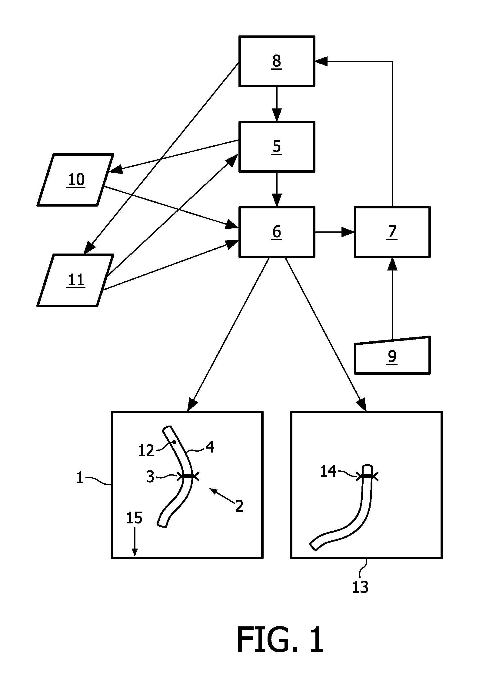
[0038]A system for visualizing a view 1 of a scene 2 is presented. The scene 2 may comprise a three-dimensional image and an object 3. The view 1 may comprise a portion of the image, for example a vessel portion 4 represented by the image. The view has a view parameter 10 associated therewith, whereas the object 3 has an object parameter 11 associated therewith.

[0039]The system may comprise view parameter establishing means 5 for establishing a first view parameter value based on a first object parameter value. The system may further comprise view visualization means 6 for visualizing the view 1 of the image in accordance with the first view parameter value. The system may further comprise interaction means 7 for enabling a user to indicate a point 12 i...


PUM


Abstract

View parameter establishing means are arranged for establishing a first view parameter value based on a first object parameter value. View visualization means are arranged for visualizing the view of the image in accordance with the first view parameter value. Interaction means are arranged for enabling a user to indicate a point in the view. Object parameter updating means are arranged for updating the object parameter based on the point to obtain a second object parameter value. The view parameter establishing means is arranged for updating the view parameter based on the second object parameter value to obtain a second view parameter value. The view visualization means is arranged for sequentially visualizing a view of the image in accordance with an intermediate view parameter value between the first view and the second view parameter values, and a view of the image in accordance with the second view parameter value.

Description

FIELD OF THE INVENTION[0001]The invention relates to visualizing a view of a scene comprising a three-dimensional image and an object, the view having a view parameter associated therewith, the object having an object parameter associated therewith. The invention also relates to medical image analysis, more particularly vessel analysis.BACKGROUND OF THE INVENTION[0002]Tools for three-dimensional visualization of three-dimensional (3D) datasets are known. In the medical field, such tools are used to support vessel analysis. These tools may offer functionality for advanced viewing, segmentation, inspection and quantification of vessels. The vessel analysis provided by such tools may support inspection of vessels by means of vessel segmentation. Some vessel analysis tools automatically track parts of a vessel structure.[0003]WO 2008 / 149274 discloses a method of inspecting tubularly shaped structures (1′) within a three-dimensional (3D) image data set, e.g. a vessel in a medical image. ...

Claims


Application Information

Patent Timeline
Patent Type & Authority Patents(United States)
IPC IPC(8): G06F3/048G06T19/00G06T15/20
CPCG06T15/20G06T19/003G06T2210/41G06T7/0012G06T19/006G06T2207/30101
Inventor HABETS, RAYMOND JOSEPH ELISABETHOLIVAN BESCOS, JAVIERPETERS, JOOSTSONNEMANS, JEROEN JOZEF
Owner KONINKLIJKE PHILIPS ELECTRONICS NV
Why Eureka
Try Eureka