
Composite internal fixators

a technology of fixator and bone, which is applied in the field of orthopedic instruments, can solve the problems of metal implant stiffness mismatch, many patients are allergic to metallic implants, and still remain

Active Publication Date: 2016-11-15
SMITH & NEPHEW INC
View PDF247 Cites 18 Cited by
  • Summary
  • Abstract
  • Description
  • Claims
  • Application Information

AI Technical Summary

Problems solved by technology

Although metal implants have been used for over a century, some problems still remain.
For example, there is a stiffness mismatch between a metal implant and bone.
Additionally, many patients are allergic to metallic implants.
Finally, some metals have a significant acquisition lead time, which may disrupt manufacturing operations.
There is difficulty in identifying the axis of the hole in the orthopaedic fixation device with which to align with the femoral head and neck.

Method used


Image

  • Composite internal fixators
  • Composite internal fixators
  • Composite internal fixators

Examples


Embodiment Construction

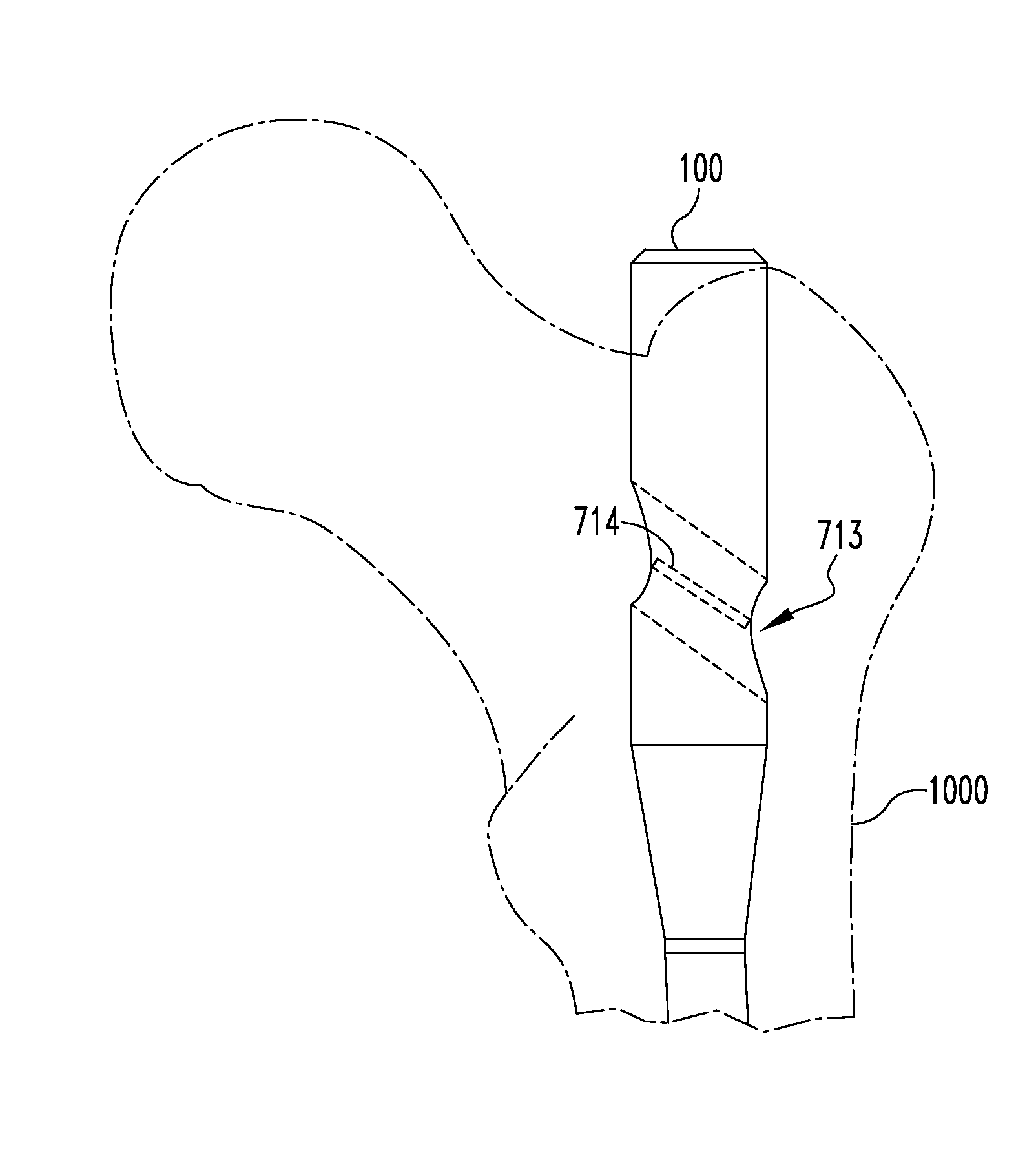
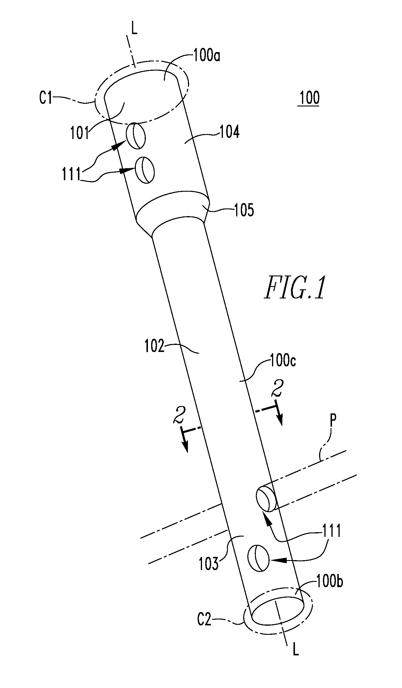
[0073]Referring to FIGS. 1, 2 and 3, an intramedullary nail 100 includes a shaft 102 and a head 104. The shaft 102 defines apertures 111 for receiving screws, or other fasteners (not shown), and the head 104 defines apertures 111 for receiving pin P, screws, or other fasteners (not shown) for securing the intramedullary nail 100 within the intramedullary canal of a long bone. The fasteners may be made from metal, polymer, or a composite material.

[0074]The nail 100 is constructed of a plurality of layers 201-213 of a composite material, such as a polyetheretherketone (PEEK) and carbon fiber composite. The composite material can be a continuous fiber-reinforced material, such as a sheet, tape, or tow, in which the carbon fibers are generally aligned in parallel with the length dimensions of the fibers oriented in the length dimension of the sheet, tape, or tow. The layers have a generally uniform thickness in the range of 0.01 millimeters to 4 millimeters, with some implementations ha...


PUM


Abstract

A multi-layer, fiber-reinforced composite orthopedic fixation device having a design selected based on a desired characteristic of the orthopedic fixation device. The design may be selected according to a model of the device, the model defining design constraints, and the design may comprise a pattern of the fiber angle for each layer. The selection of a design may be analyzed using finite element analysis to determine whether the design will comprise the desired characteristic.

Description

CROSS-REFERENCE TO RELATED APPLICATIONS[0001]This application claims the benefit of U.S. Provisional Application No. 61 / 105,717, filed 15 Oct. 2008, and U.S. Provisional Application No. 61 / 180,403, filed 21 May 2009. The disclosure of each application is incorporated by reference in its entirety.BACKGROUND OF THE INVENTION[0002]The present invention relates generally to orthopedic instrumentation and more specifically to internal fixation devices.[0003]Orthopaedic fixation devices may be used, for example, to stabilize an injury, to support a bone fracture, to fuse a joint, or to correct a deformity. The orthopaedic fixation device may be attached permanently or temporarily, and may be attached to the bone at various locations, including implanted within a canal or other cavity of the bone, implanted beneath soft tissue and attached to an exterior surface of the bone, or disposed externally and attached by fasteners, such as screws, pins, and / or wires. Some orthopaedic fixation devi...

Claims


Application Information

Patent Timeline
Patent Type & Authority Patents(United States)
IPC IPC(8): A61B17/72A61B17/80A61B17/00
CPCA61B17/72A61B17/80A61B17/7216A61B17/7283A61B90/39A61B2017/00022A61B2017/00411A61B2017/00415A61B2017/00526A61B2017/00734A61B2017/00831A61B2017/00955A61B2090/0436A61B2090/064A61B17/7225
Inventor RAINS, JAMES K.AUSTIN, GENE EDWARDROSE, JOHN NMIFERRANTE, JOSEPH MICHAELGERLACH, DARIN S.GRUSIN, NATHANIEL KELLEYJANNA, SIED W.FABER, HENRY B.GOSNEY, MARK S.WILSON, DARREN JAMES
Owner SMITH & NEPHEW INC
Learn More