
Modular boat lift cover

a boat lift and module technology, applied in the field of modules, can solve the problems of difficult design, manufacture and installation of boat lift covers for tidal lifts, difficult to meet the needs of tidal lifts, and inconvenient configuration, and achieve the effect of wide adjustment range and convenient configuration

Inactive Publication Date: 2016-11-08
CRAIG ERIC N
View PDF27 Cites 3 Cited by
  • Summary
  • Abstract
  • Description
  • Claims
  • Application Information

AI Technical Summary

Benefits of technology

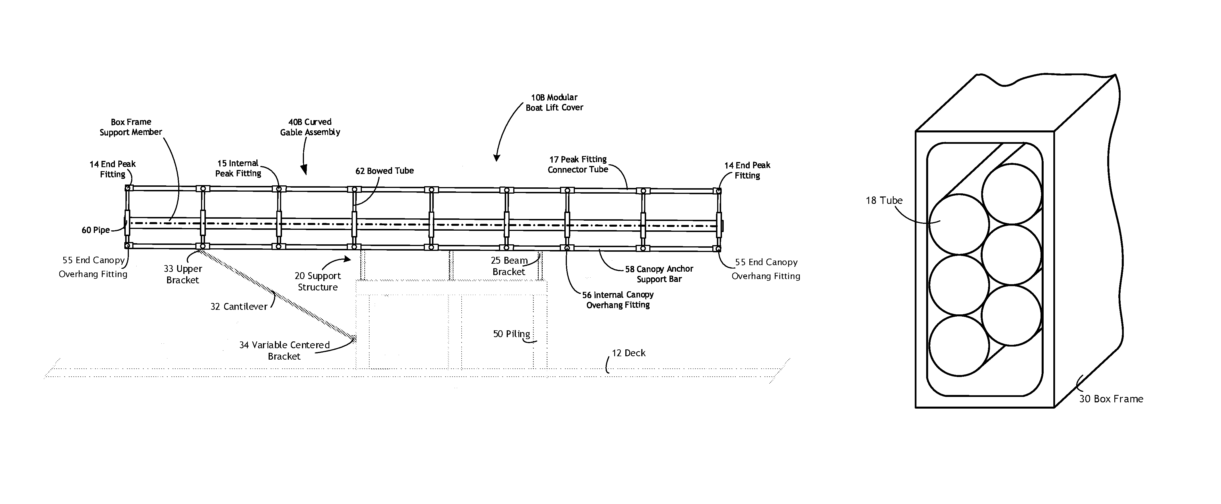
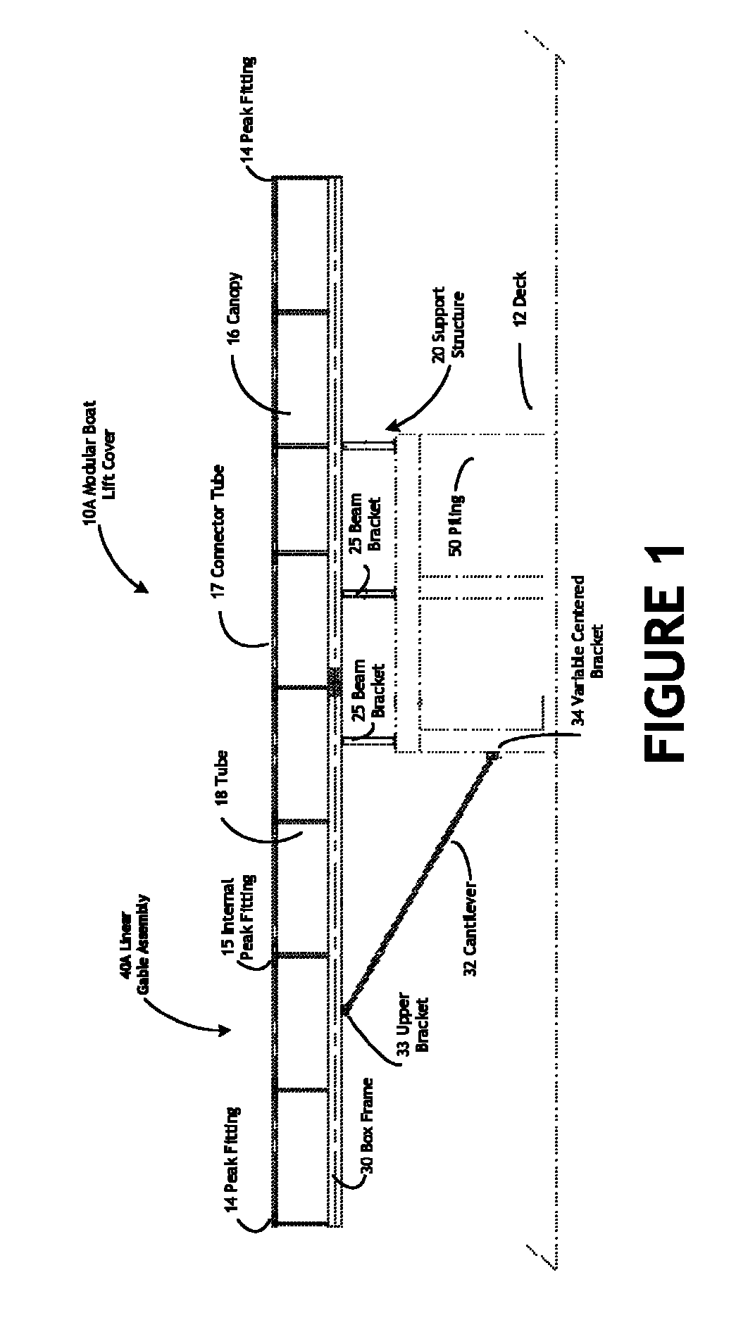
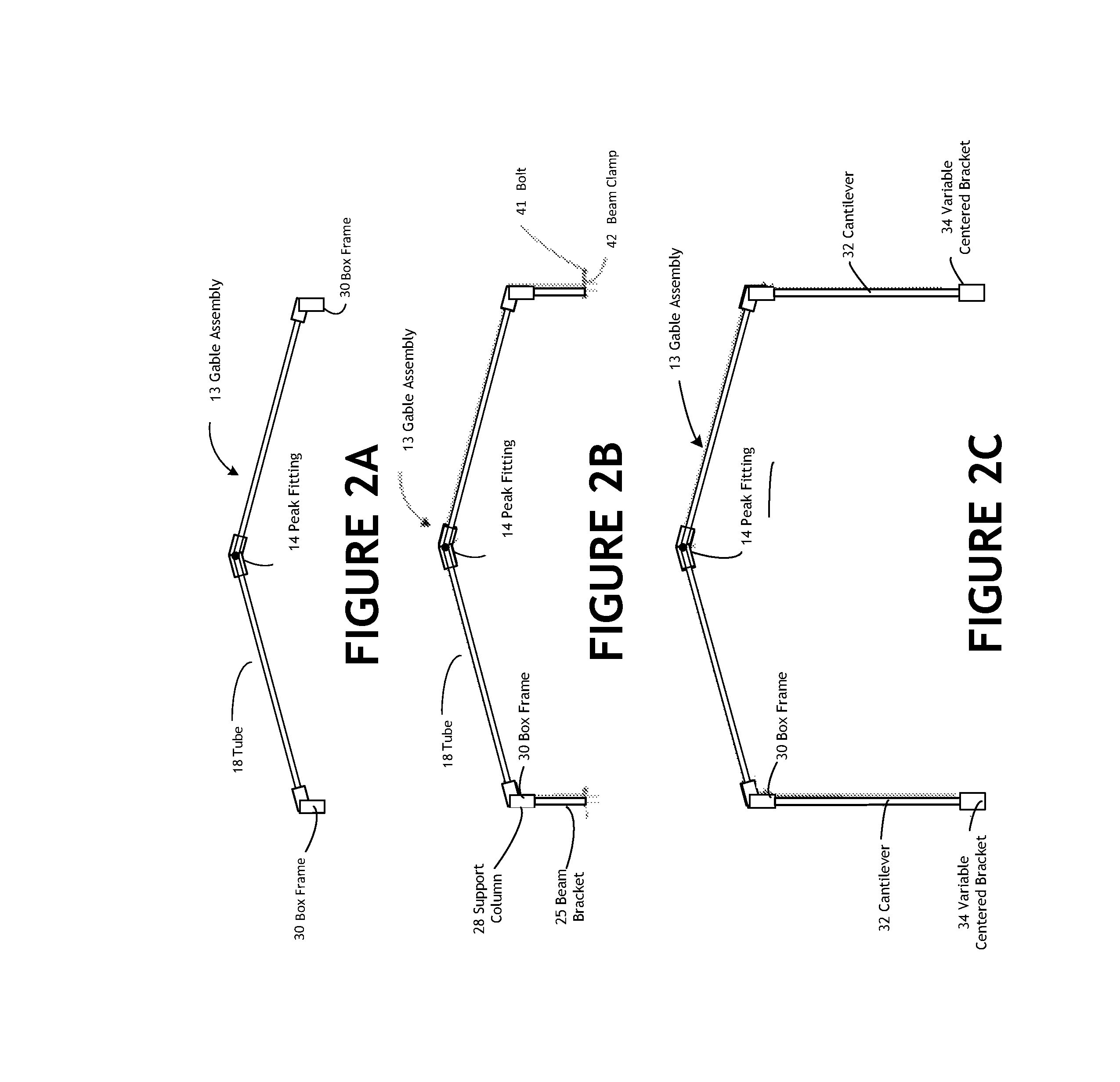
[0019]The modular boat lift cover of the present invention is preferably supported by a pair of cantilevers mounted on each by a bracket and secured to a box frame support member, said upper bracket being needed to support the gable assembly, which supports the canopy. It will be noted that the pair of cantilevers secured to each box frame support member are needed to support the modular boat lift cover of the present invention. The cantilevers in combination with the box frame channels have sufficient bulk to store the gable components during transport will protect the watercraft from the elements and withstand even the severest of storms, undamaged. The pair of cantilevers are secured to each box frame with an upper bracket and the pair of cantilevers are secured to the deck assembly with a variable centered bracket. The plurality of peak fittings are positioned on the gable assembly, the peak fittings being connected by at least one peak fitting connector tube.
[0026]All of the length, width and height assemble points are designed to have a wide range of adjustment. This wide range of adjustment is what enables the modular boat lift cover of the present invention to accommodate boat lifts from any manufacturer as well as accommodating square lake lifts and out-of-square tidal lifts. In addition, the range of adjustment enables for easy configuration for different sizes of watercraft.
[0027]The modular boat lift cover of the present invention combines the advantages is a portable structure which in its collapsed state forms a standard shipping container for ease of transport.

Problems solved by technology

While boat houses can provide such shelter, they are expensive, often impractical and, under some circumstances, not allowed by code.
This construction technique is subject to tidal forces during the time that the pilings are being hammered into the sea floor, which can cause the lift to be not perfectly square.
Additionally, each boat lift manufacturer has its own design for the lifting I-beam, the cable system and the position of the electric motors making it difficult to design, manufacture and install a boat lift cover for tidal lifts.
By constructing a special frame that incorporates a drive-through curtain system and also a peak in the canopy structure itself, the wakeboard boat being enabled to pull into the normal lift with enough clearance for the tower from the canopy frame.The packaging of boat lift covers and canopies currently being marketed is overly-complicated and costly, and assembly is difficult to explain even with instructions.In order to communicate the intricacies of assembly and disassembly, personal demonstrations are often required.
If the complicated unpacking was not difficult enough, the procedure for layout and assembly of the frame is oftentimes even more complex.
In addition to the difficulty of assembly, current boat lift covers cannot be easily adjusted if the lift owner modifies his boat, such as by adding a tower, or replaces his boat with, for example, a larger boat.
Current boat lift cover designs have some degree of adjustability but are not adjustable enough to easily accommodate all boat lift mechanisms and the dimensional tolerance variations of tidal lifts.
In addition, a further limitation of the prior art boat lift canopies, in general, is that they are not designed to maximize the structural inherent in truss type framework structures.
Long unsupported overhangs, which are becoming increasingly popular, require that newer canopy configurations require considerable structural strength.

Method used


Image

  • Modular boat lift cover
  • Modular boat lift cover
  • Modular boat lift cover

Examples


Embodiment Construction

[0066]Referring now to the drawings, FIG. 1 depicts a preferred embodiment of an assembly side view of the modular boat lift cover of the present invention [10A]. The modular boat lift cover of the present invention [10A] comprises a gable assembly [13], a canopy [16], and an adjustable support structure [20] for a watercraft.

[0067]The gable assembly [13] includes a plurality of end peak fittings [14] and internal peak fittings [15], as further depicted in FIGS. 5A, 5B, 5C, 5D, a plurality of box frame support members [30], and a plurality of tubes [18] securely attaching the end peak fittings [14] and the internal peak fittings [15] to the box frame support members [30]. The box frame support members [30] are preferably horizontally mounted in the gable assembly [13] and cantilevered out from the piling [50] upon which the beam brackets [25] are attached if necessary for applications in which the piling [50] is not arrayed as desired for a given size boat or watercraft. In the cant...


PUM


Abstract

The modular boat lift cover for a watercraft comprises a gable assembly and an adjustable support structure. All of the straight components are packaged into the main box frame channels for simplicity in packaging as well as quality control, ensuring no components are missing during packaging and shipping. The box frame channels have sufficient bulk to store the gable components during transport. The modular boat lift cover system has a robust, lightweight design that is compatible and adjustable for width, height and length as the boat owner modifies his existing boat or purchases a new boat, and that will protect the watercraft from the elements and will withstand even the severest of storms, undamaged as well as having the ability to be cantilevered. The modular boat lift cover is easy for the user to assemble and adjust on square lake style boat lifts, and the typically non-square tidal lifts.

Description

CROSS-REFERENCE TO RELATED APPLICATIONS[0001]This Application is a Continuation-In-Part and claims priority to U.S. Provisional Application No. 62 / 077,522, entitled “Modular Boat Lift Cover,” filed on Nov. 10, 2014; and U.S. patent application Ser. No. 14 / 636,409 entitled “Modular Boat Lift Cover,” filed on Mar. 3, 2015.FIELD OF USE[0002]The present invention relates to a modular boat lift cover system which is designed for ease of shipping and assembly as well as adjustability as the lift owner changes or modifies their boat. The modular boat lift cover being unique in that it can accommodate all boat lifts that are square, such as lake lifts, as well as tidal lifts which, due to their nature of construction, are seldom square.BACKGROUND OF THE INVENTION[0003]A watercraft represents a significant investment. Watercraft owners' who store their boats on lifts understand that a boat lift cover or canopy is needed to minimize the maintenance work required to maintain the appearance of ...

Claims


Application Information

Patent Timeline
Patent Type & Authority Patents(United States)
IPC IPC(8): E04H15/36E04H15/44B63B17/02E04H15/32E04H15/18E04H15/00E04H15/40B63C3/00
CPCB63B17/02E04H15/00E04H15/18E04H15/32E04H15/36B63C3/00E04H15/40E04H15/34E04H15/44E04H15/644
Inventor CRAIG, ERIC N
Owner CRAIG ERIC N
Learn More