
Laser scanner

Active Publication Date: 2016-10-25
SICK AG
View PDF14 Cites 12 Cited by
  • Summary
  • Abstract
  • Description
  • Claims
  • Application Information

AI Technical Summary

Benefits of technology

The invention describes a method for improving the detection and differentiation of objects from disturbance phenomena in a monitored area using light beams with aligned polarization directions. The method involves analyzing the reflected light signals to determine the contribution of light reflected from objects and from disturbance phenomena. By evaluating the polarization components of the reflected light, the system can better identify and differentiate objects from feed-back signals caused by disturbance phenomena. The system can also adjust the power of the light transmission based on the evaluation of the reflected light signals, to ensure sufficient light reaches the detection unit even with reduced visibility. The use of two light transmitters with aligned polarization directions and identical wavelength or frequency spectrum can further enhance the object detection and visibility impairment detection.

Problems solved by technology

Hard objects are generally safety-critical in safety applications and have to be recognized.

Method used


Image

  • Laser scanner
  • Laser scanner
  • Laser scanner

Examples


Embodiment Construction

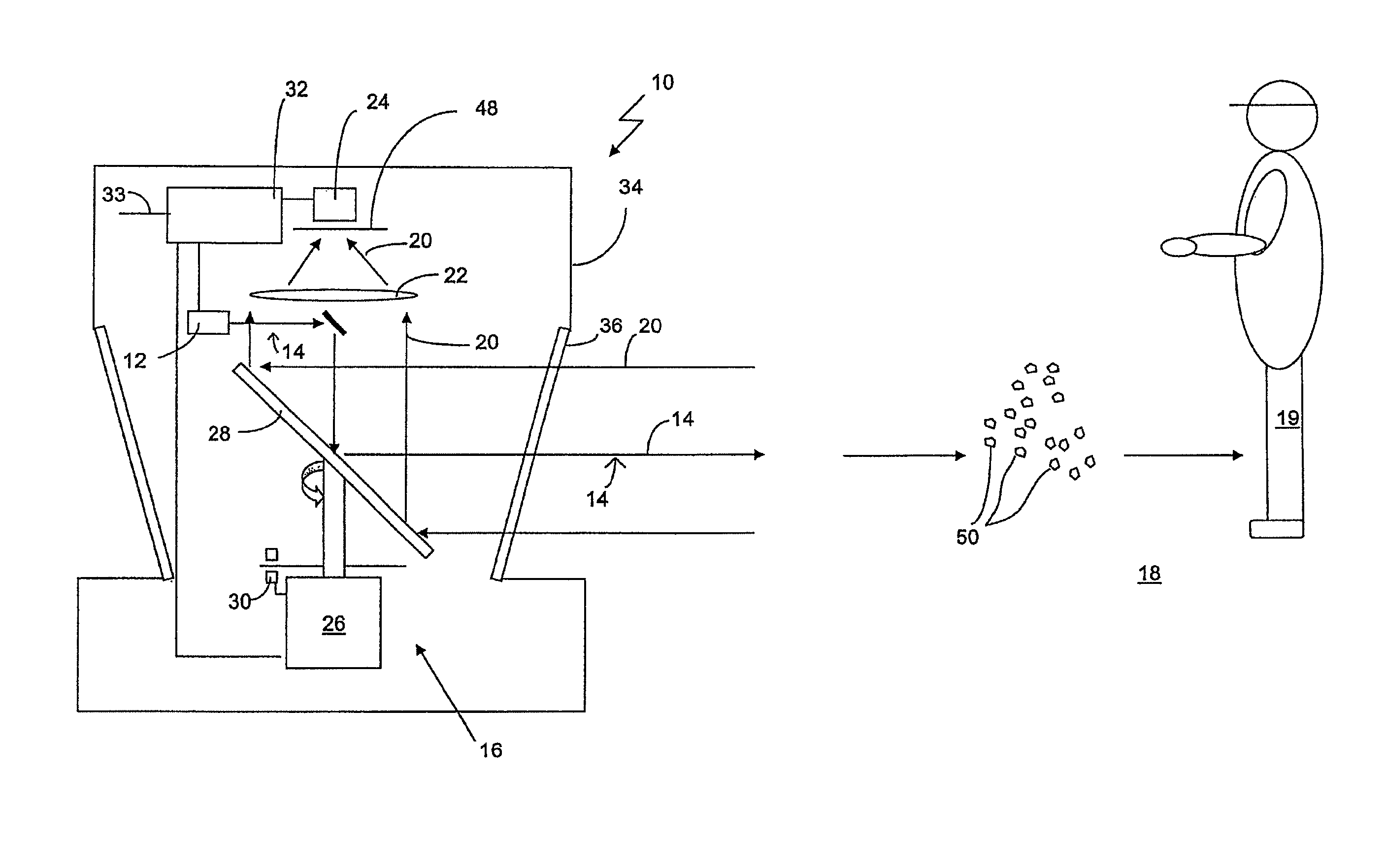
[0040]A safety laser scanner described in the following serves, for example, for monitoring for unauthorized access into a monitored zone or for monitoring the region in front of an autonomously driving vehicle. If an unpermitted object, for example the leg of an operator, is located in the monitored zone, this is detected by the described scanner and a safety signal, which can be a warning signal or a switching-off signal, can be output and corresponding measures are initiated which prevent the danger, e.g. the movement of the machine causing danger is stopped or at least braked.

[0041]The term “unauthorized object” is used in the present text for unauthorized objects in the protected field which have to be detected to prevent a danger, e.g. a collision. Endangered body parts of operators can in particular be meant by it, for example.

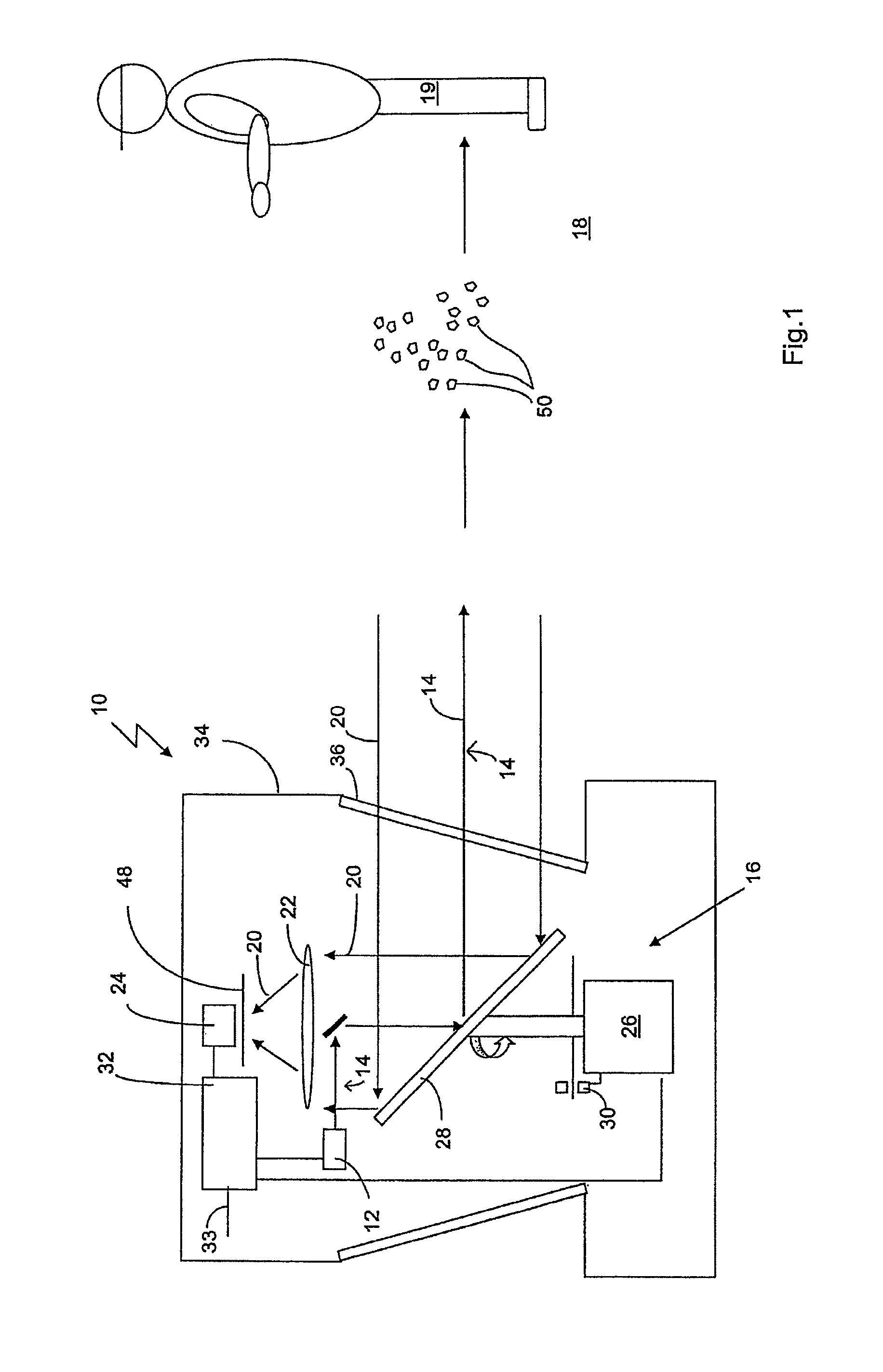
[0042]FIG. 1 schematically shows the design of an embodiment of a safety laser scanner 10. A laser light beam 14 which is generated by a light transmit...


PUM


Abstract

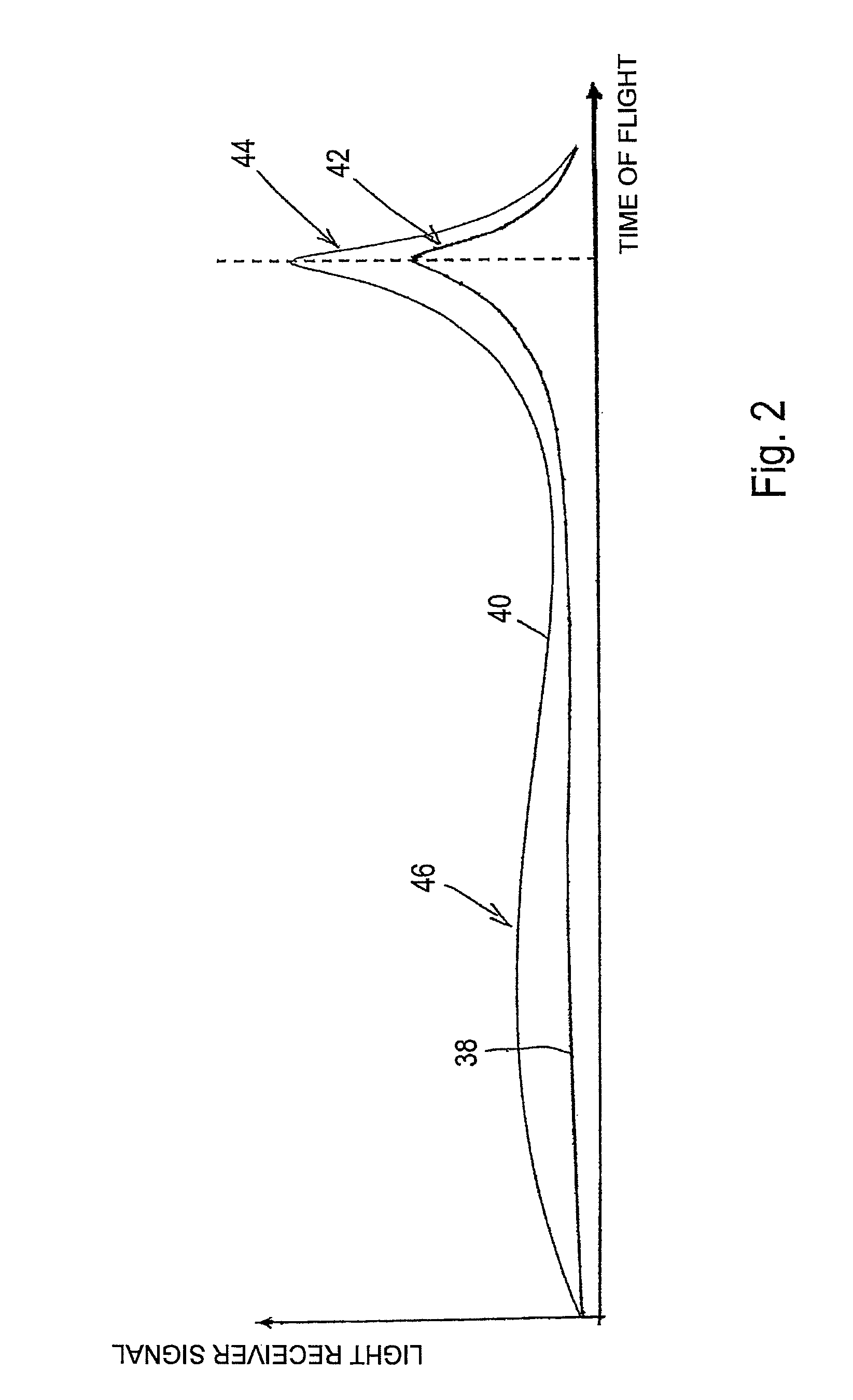
A laser scanner, in particular a safety laser scanner, in accordance with the operating principle of the time of flight process, comprising a light transmission unit having at least one light transmitter for transmitting a polarized transmitted light beam into a monitored zone; a light reception unit having at least one light receiver for detecting the polarization component of the light reflected in the monitored zone being orthogonal to the polarization direction of the transmitted light beam, and / or the polarization component of the light reflected in the monitored zone being parallel to the polarization direction of the transmitted light beam, and for generating a received signal corresponding to the detected orthogonal polarization component and / or the detected parallel polarization component; and an evaluation unit configured to evaluate the time development of the detected orthogonal polarization component and / or of the detected parallel polarization component.

Description

BACKGROUNDTechnical Field[0001]The present invention relates to a laser scanner, in particular to a safety laser scanner, in accordance with the operating principle of the time of flight process for detecting objects in a monitored zone.[0002]The presence and the distance of objects can be determined in accordance with the known principle of the time of flight process using laser scanners. For this purpose, either a brief light pulse is transmitted and the time until the reception of a reflection of the light pulse is measured in a pulse transit time process or transmitted light is amplitude-modulated and a phase shift between the transmitted light and the received light is determined in a phase process, with the phase shift likewise being a measure for the time of flight.[0003]Safety laser scanners such as are known, for example, from DE 43 40 756 A1 are frequently used for monitoring work areas. A light beam generated by a laser is directed via a light deflection unit into a prote...

Claims


Application Information

Patent Timeline
IPC IPC(8): G01V8/10G01S17/93G01S7/499
CPCG01V8/10G01S7/499G01S17/93
Inventor ALBERT, MAGNUSENGLER, MICHAELKRAMER, JOACHIM
Owner SICK AG
Learn More