System and method for reducing engine oil dilution

a technology of engine oil and dilution reduction, which is applied in the direction of machines/engines, electric control, combustion engines, etc., can solve the problems of excessive dilution of engine oil, fuel odors perceptible by the vehicle operator, and fuel dilution of the engine oil can occur, so as to reduce excess oil dilution and improve emissions.

Inactive Publication Date: 2016-10-18
FORD GLOBAL TECH LLC
View PDF21 Cites 7 Cited by
  • Summary
  • Abstract
  • Description
  • Claims
  • Application Information

AI Technical Summary

Benefits of technology

[0003]Treharne et al. (US 2013 / 0268182) describes a method of reducing oil contamination in a hybrid vehicle by starting an engine if the energy stored in an energy storage device is greater than an upper threshold level when a contaminant amount in engine oil is greater than a threshold amount. Herein, engine is run inefficiently to increase heat output and thereby, reduce oil contamination. The inventors herein have recognized potential issues with the above approach. Namely, during the inefficient engine operation, the engine may be operated with late fuel injection timing in order to increase heat output as well as to reduce particulate matter emissions, and operating a vehicle engine with late fuel injection timing can increase oil dilution, especially during repeated cold engine starts before the engine has warmed up.
[0008]In this way, by adjusting fuel injection timing in response to an oil dilution amount, the oil dilution amount based on the commanded air-to-fuel ratio and the engine air-to-fuel ratio, excess oil dilution may be reduced and emissions may be improved.

Problems solved by technology

During cold engine operation, including cold engine starts, if the engine does not reach stable engine operating conditions, fuel dilution of the engine oil can occur.
Repeated cold start engine operation without completing engine warm-up may result in excessive fuel dilution and degradation of oil quality.
Further, this can cause oil overfill conditions which in turn may generate fuel odors perceptible by the vehicle operator.
Herein, engine is run inefficiently to increase heat output and thereby, reduce oil contamination.

Method used


Image

  • System and method for reducing engine oil dilution
  • System and method for reducing engine oil dilution
  • System and method for reducing engine oil dilution

Examples


Embodiment Construction

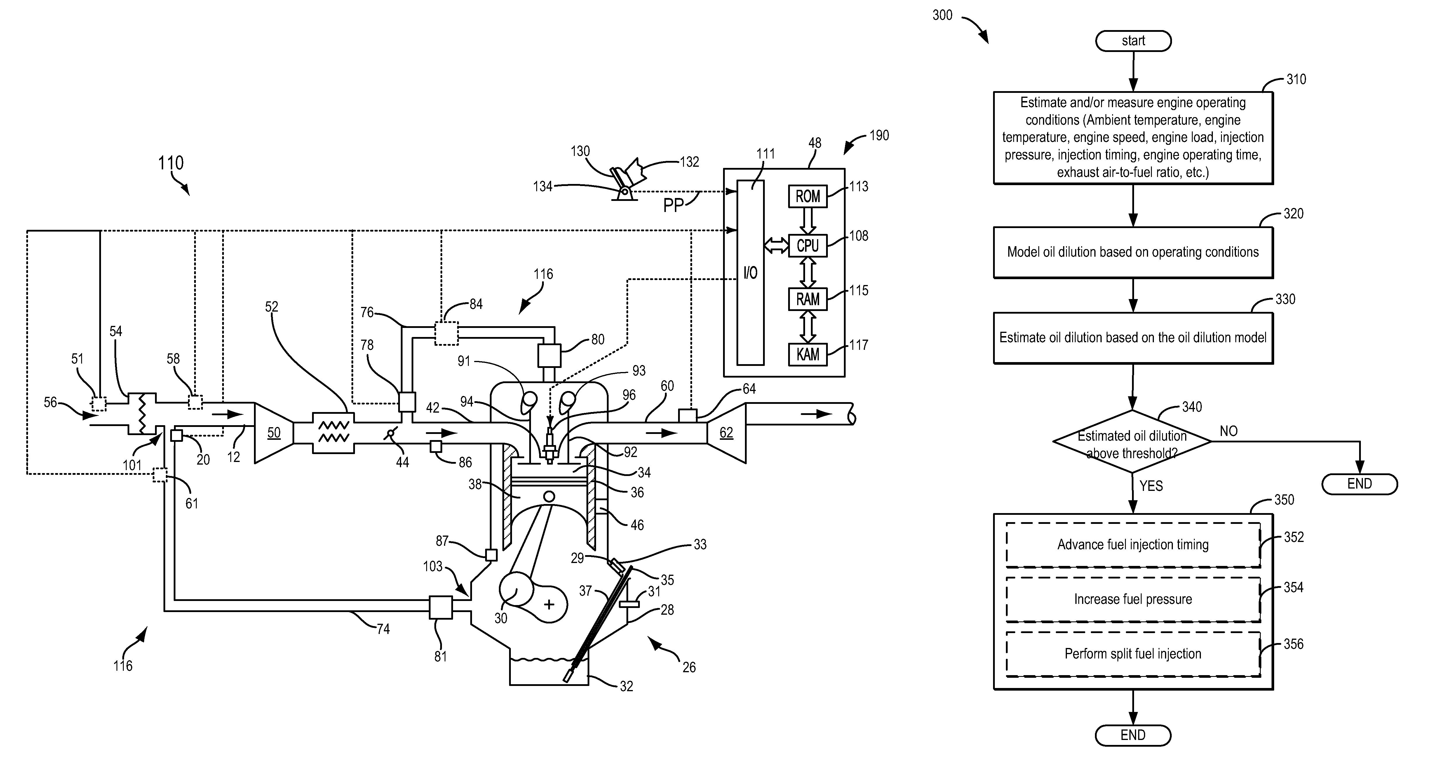
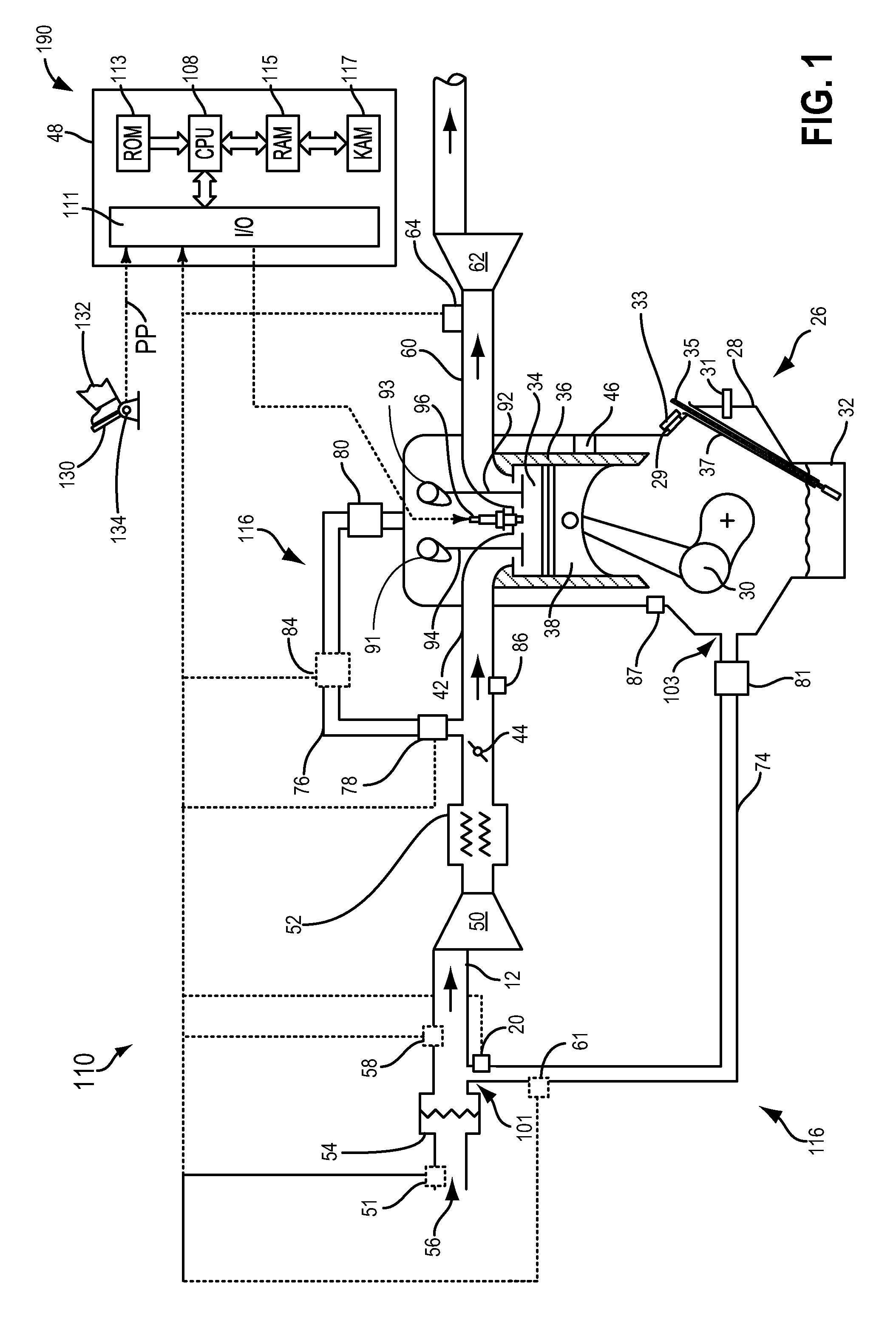
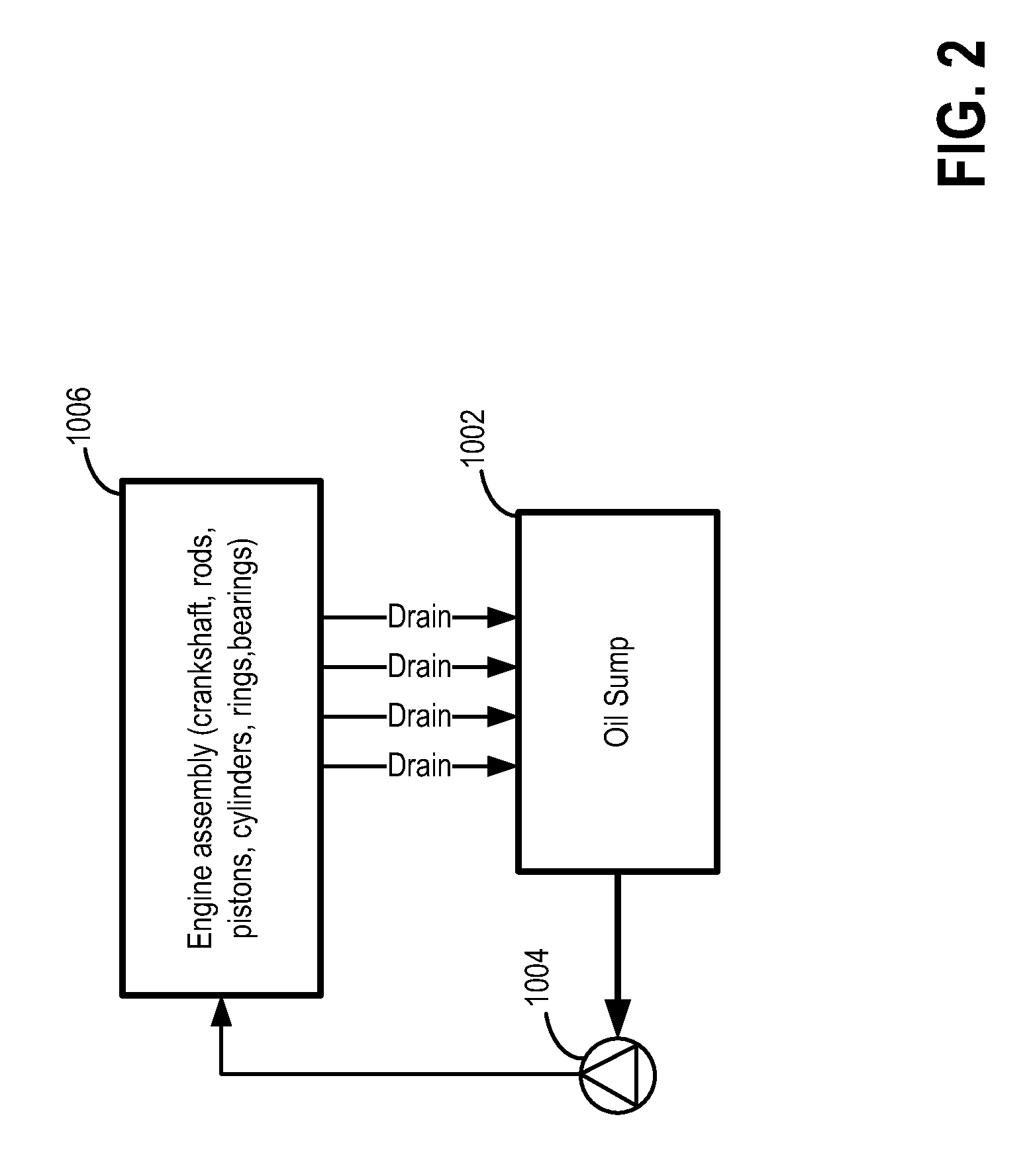
[0016]The following description relates to systems and methods for adjusting engine fuel injection timing based on an oil dilution amount in an engine system, such as the engine system of FIG. 1. Oil flow in a lubrication system of the engine system of FIG. 1 is shown at FIG. 2. An engine controller may perform a control routine, such as the routine of FIG. 3, to determine an oil dilution amount, and the controller may adjust fuel injection timing to mitigate oil dilution when the oil dilution amount is greater than the threshold. Further, when the oil dilution amount is less than the threshold, fuel injection timing may be adjusted to reduce engine emissions. The oil dilution amount may be determined based on an integrated difference between a commanded air-to-fuel ratio and an engine air-to-fuel ratio. Example oil dilution amount adjustments based on the air-to-fuel ratios, and fuel injection timing adjustments based on the oil dilution amount are shown at FIGS. 4-5.

[0017]FIG. 1 s...


PUM


Abstract

Methods and systems are provided for modeling an oil dilution qualitative indicator based on an integrated difference between a commanded air-to-fuel ratio and an engine air-to-fuel ratio as determined via an oxygen sensor, cumulative cold engine temperature operating duration, and fuel injection characteristics (timing, duration, number of injections) allowing fuel injection timing modifications that minimize oil dilution when the oil dilution qualitative indicator is greater than a threshold level.

Description

FIELD[0001]The present disclosure relates to systems and methods for reducing engine oil dilution.BACKGROUND AND SUMMARY[0002]During cold engine operation, including cold engine starts, if the engine does not reach stable engine operating conditions, fuel dilution of the engine oil can occur. For example, fuel may mix with engine oil in an engine's crankcase. Repeated cold start engine operation without completing engine warm-up may result in excessive fuel dilution and degradation of oil quality. Further, this can cause oil overfill conditions which in turn may generate fuel odors perceptible by the vehicle operator.[0003]Treharne et al. (US 2013 / 0268182) describes a method of reducing oil contamination in a hybrid vehicle by starting an engine if the energy stored in an energy storage device is greater than an upper threshold level when a contaminant amount in engine oil is greater than a threshold amount. Herein, engine is run inefficiently to increase heat output and thereby, re...

Claims


Application Information

Patent Timeline
Patent Type & Authority Patents(United States)
IPC IPC(8): F02D41/40F02D41/06
CPCF02D41/401F02D41/064F02D2200/021F02D2250/11Y02T10/44Y02T10/40
Inventor LEHMEN, ALLENFRIED, MARCUS WILLIAMYAMADA, SHUYA SHARKPENKEVICH, STEVEN PAUL
Owner FORD GLOBAL TECH LLC
Why Eureka
Try Eureka