
Quality-control jig for use with radiotherapy apparatus

a quality control and igrt technology, applied in the field of radiotherapy, can solve the problems of time-consuming and complicated procedures

Inactive Publication Date: 2016-10-18
UNIV OF FLORIDA RES FOUNDATION INC
View PDF8 Cites 3 Cited by
  • Summary
  • Abstract
  • Description
  • Claims
  • Application Information

AI Technical Summary

Problems solved by technology

However, such procedures are time-consuming and complicated.

Method used


Image

  • Quality-control jig for use with radiotherapy apparatus
  • Quality-control jig for use with radiotherapy apparatus
  • Quality-control jig for use with radiotherapy apparatus

Examples


Embodiment Construction

[0020]The Figures herein are not necessarily to scale; various components may be enlarged or reduced for clarity of illustration. The same element is always indicated by the same reference numeral in all the Figures.

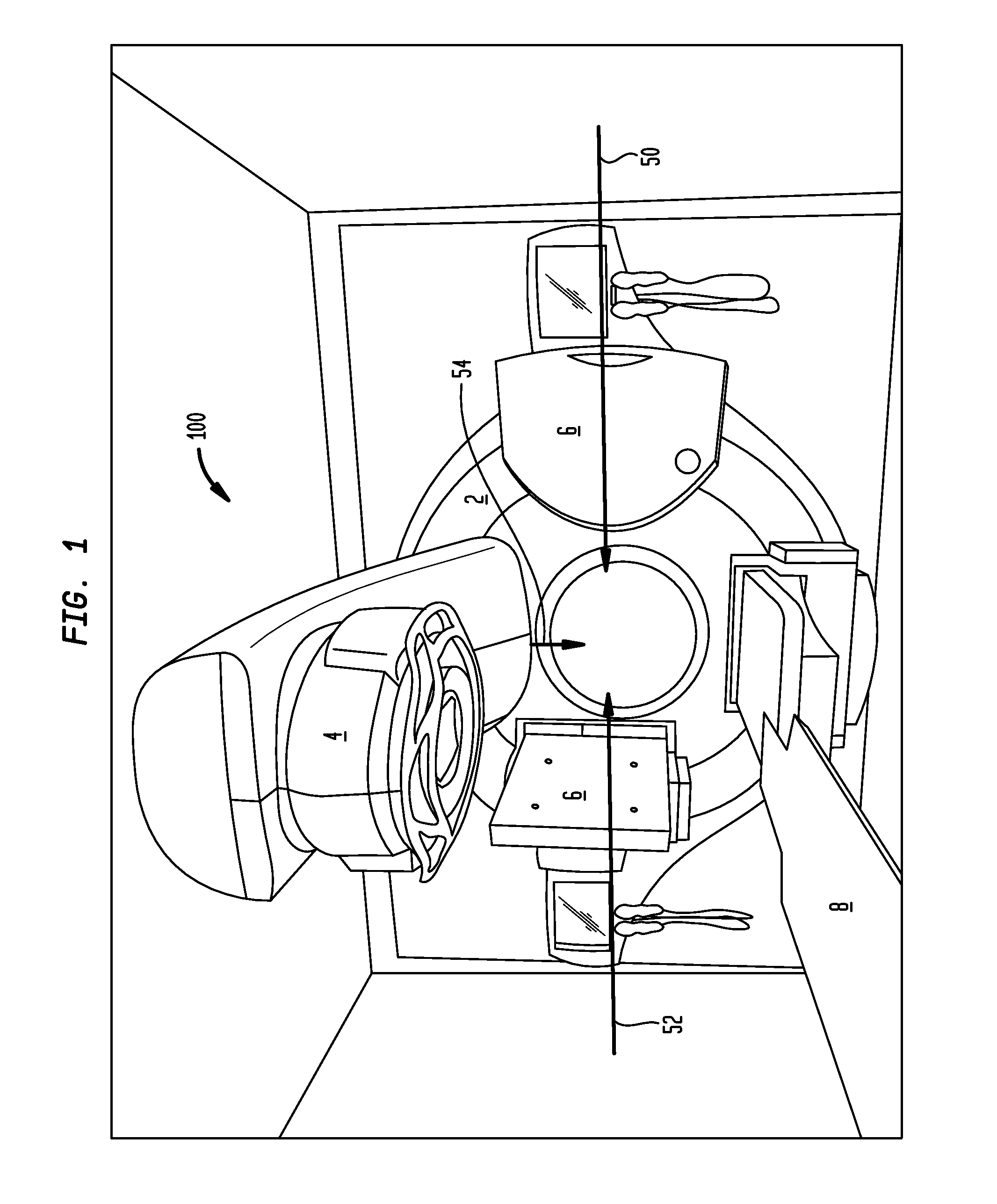
[0021]FIG. 1 shows a conventional image-guided radiation therapy (“IGRT”) apparatus generally indicated by reference numeral 100. A toroidal gantry 2 is supported to rotate in a vertical plane. A linac 4 is attached to the gantry 2, as is an imager 6. (In this example, the imager 6 is a cone-beam computed tomography imager, but this is not required. Another imaging device, such as an X-ray apparatus, can be used instead.)

[0022]The IGRT apparatus 100 has a patient table 8; in use, a patient (not shown) is supported on the table 8. Initially, the table 8 and the imager 6 are adjusted so that the imager 6 is aimed at the body region where a tumor (likewise not shown) is located. In an initial imaging phase, the gantry 2 is rotated while the imager 6 is operated to acquire i...


PUM


Abstract

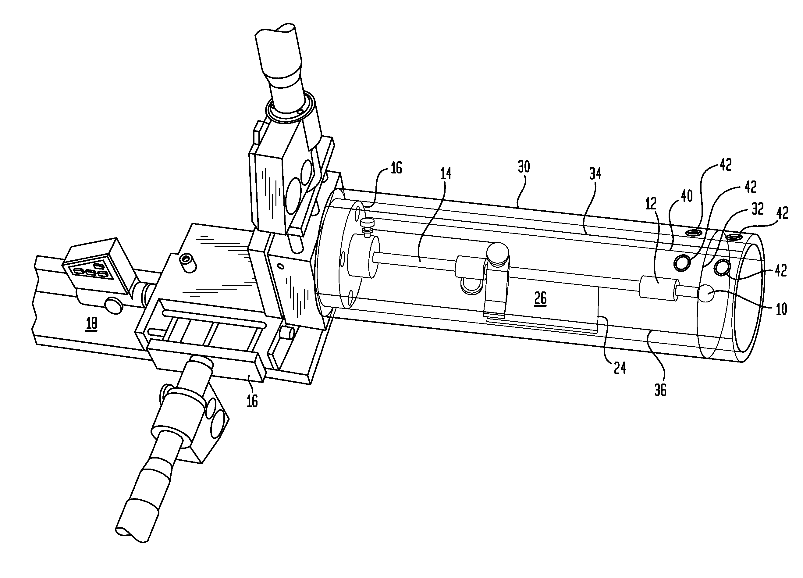
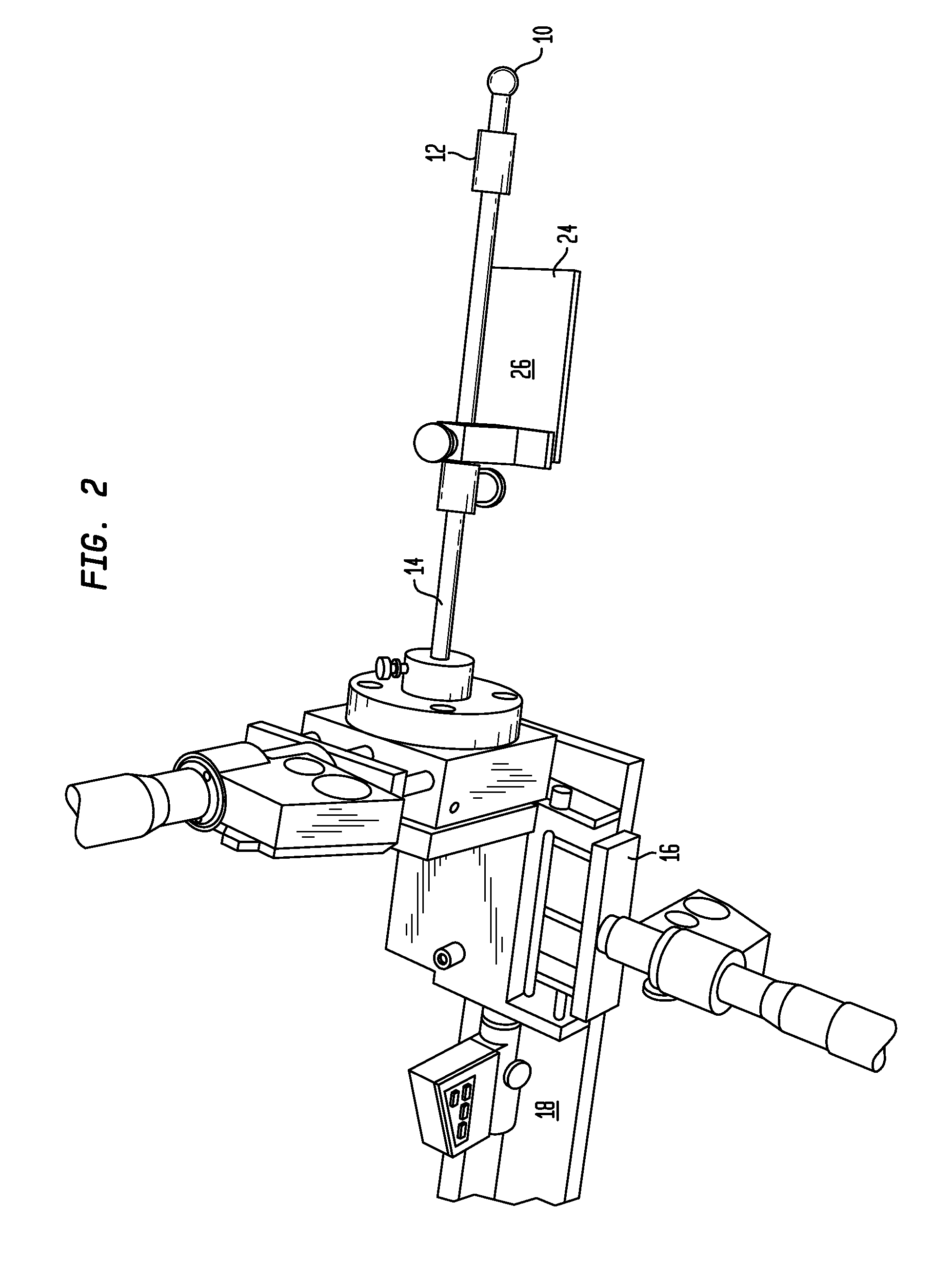
A jig for calibrating an image-guided radiotherapy apparatus is disclosed. The jig includes a ball bearing and a three-axis positioner. Once the ball bearing has been moved to the calculated radiation isocenter of the apparatus, other calibration procedures can be performed by directing light onto the jig.

Description

BACKGROUND OF THE INVENTION[0001]The invention relates to radiotherapy, and more particularly relates to image-guided radiotherapy (“IGRT”). In its most immediate sense, the invention relates to a quality-control jig for use with IGRT apparatus.[0002]In IGRT apparatus, two instruments are mounted upon a rotatable gantry. One of these is a linear accelerator (a “linac”). The linac produces a beam of high-energy radiation (the “treatment beam”) used to destroy tumor tissue inside the patient's body. The other is an imager (which is usually but not necessarily a cone-beam computed-tomography imager). This produces a lower-energy beam of radiation (the “imaging beam”) used to create a three-dimensional image of the patient's body region in which the patient's tumor is located. The linac's treatment beam and the imager's imaging beam are at right angles to each other.[0003]Before a patient is imaged and subjected to radiation therapy, it is necessary to make sure that the IGRT apparatus ...

Claims


Application Information

Patent Timeline
Patent Type & Authority Patents(United States)
IPC IPC(8): A61B6/04A61B6/08A61N5/10G09B23/28A61B6/00
CPCA61B6/584A61B6/0492A61B6/547A61B6/589A61N5/1049A61B6/08A61N5/1075A61N2005/1076G09B23/286
Inventor LIU, CHIHRAYYAN, GUANGHUA
Owner UNIV OF FLORIDA RES FOUNDATION INC
Learn More