
Screw assembling device

a screw and assembly device technology, applied in the direction ofauxillary welding devices, soldering devices, manufacturing tools, etc., can solve the problems of large amount of screws to be assembled, small screw size, and difficult manual holding and positioning

Inactive Publication Date: 2016-09-20
SHENZHEN FUTAIHONG PRECISION IND CO LTD +1
View PDF4 Cites 0 Cited by
  • Summary
  • Abstract
  • Description
  • Claims
  • Application Information

AI Technical Summary

Benefits of technology

The patent text discusses the problem of assembling electronic devices with screws, which is difficult and time-consuming due to the small size of the screws and the large amount of screws needed. The technical effect of the patent is to provide an automatic way to assemble screws, which would save time and make the assembly process easier and more efficient.

Problems solved by technology

However, the screws are small in size, which makes them hard to hold and position manually.
In addition, the amount of screws to be assembled is great, which costs a lot of time.

Method used


Image

  • Screw assembling device
  • Screw assembling device
  • Screw assembling device

Examples


Embodiment Construction

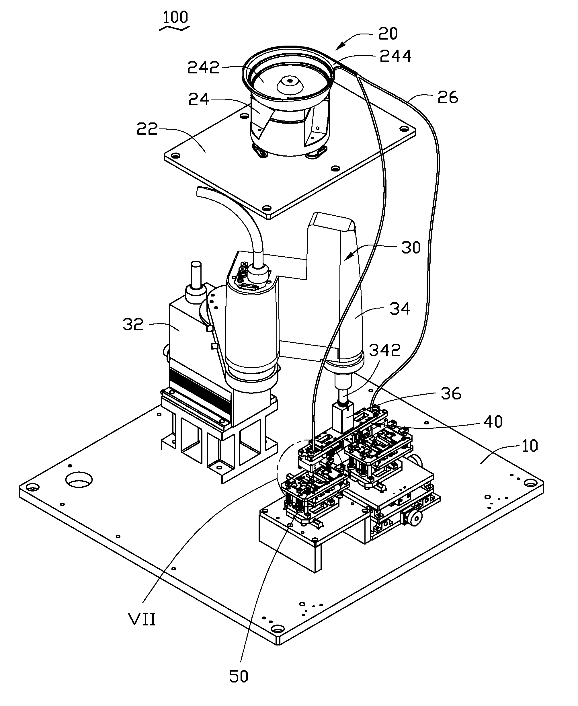
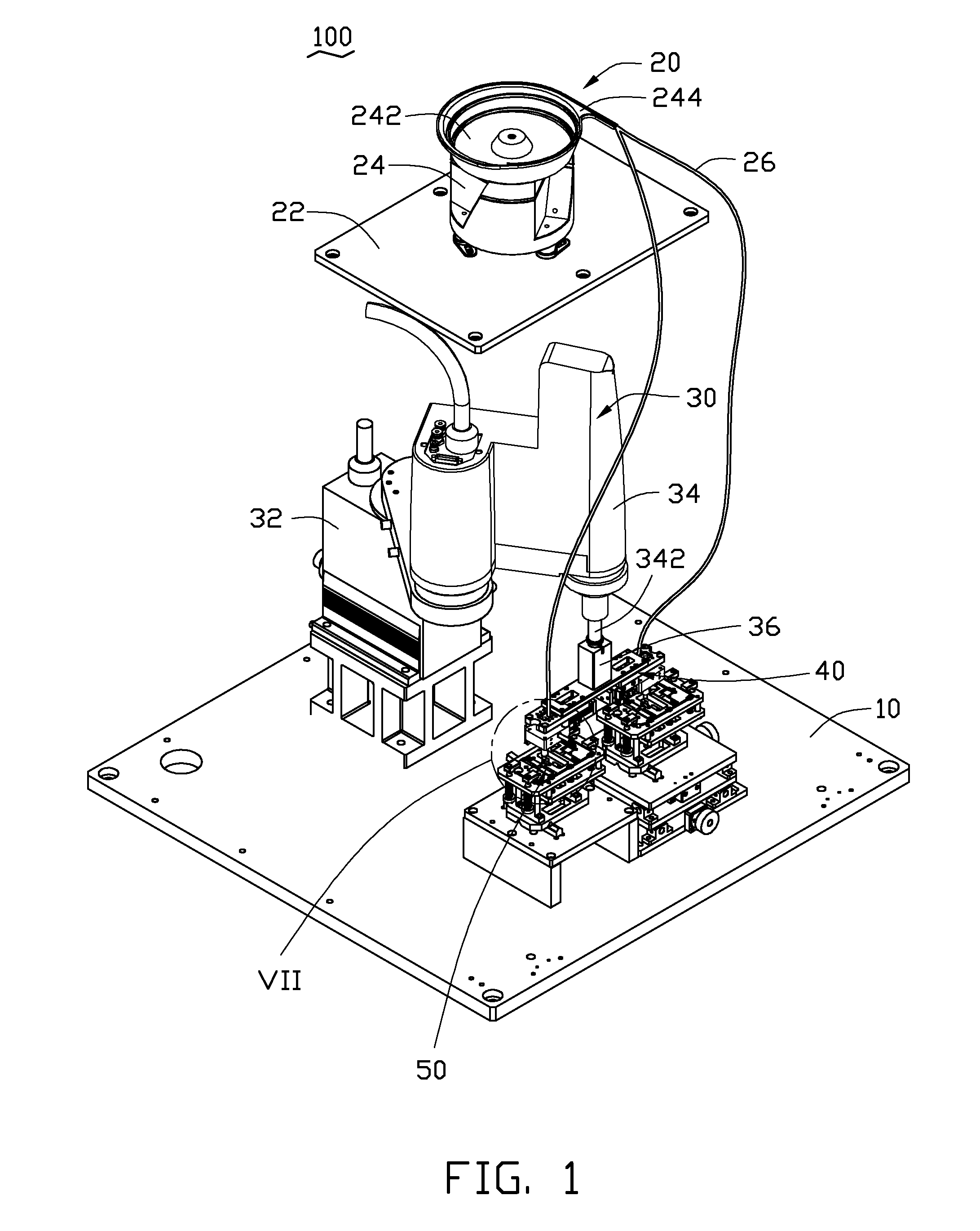
[0013]Referring to FIG. 1, an screw assembling device 100 according to an exemplary embodiment assembles screws into housings of electronic devices. The screw assembling device 100 includes a platform 10, a supplying mechanism 20, a driving mechanism 30, an assembling mechanism 40, and a securing mechanism 50. The driving mechanism 30 and the securing mechanism 50 are located on the platform 10. The supplying mechanism 20 is located above the driving mechanism 30. The assembling mechanism 40 is located between the driving mechanism 30 and the securing mechanism 50.

[0014]The supplying mechanism 20 includes a board 22, a plurality of columns (not shown), a material provider 24, and a pair of tubes 26. The columns are disposed on the platform 10 to support the board 22. The material provider 24 includes a circular tray 242 on an upper portion thereof and a port 244 connected to a side of the tray 242. The tray 242 holds materials, such as screws. The pair of tubes 26 are connected to t...


PUM

PropertyMeasurementUnit
movementaaaaaaaaaa
sizeaaaaaaaaaa
frequencyaaaaaaaaaa

Abstract

An screw assembling device includes a supplying mechanism, a securing mechanism, a driving mechanism, and an assembling mechanism. The supplying mechanism supplies a number of screws sequentially. The securing mechanism holds a housing of an electronic device. The assembling mechanism is connected to the supplying mechanism and the driving mechanism. The assembling mechanism is driven by the driving mechanism to predetermined positions of the housing of electronic device and is configured for assembling the plurality of screws transmitted from the supplying mechanism to the predetermined positions of the housing of electronic device.

Description

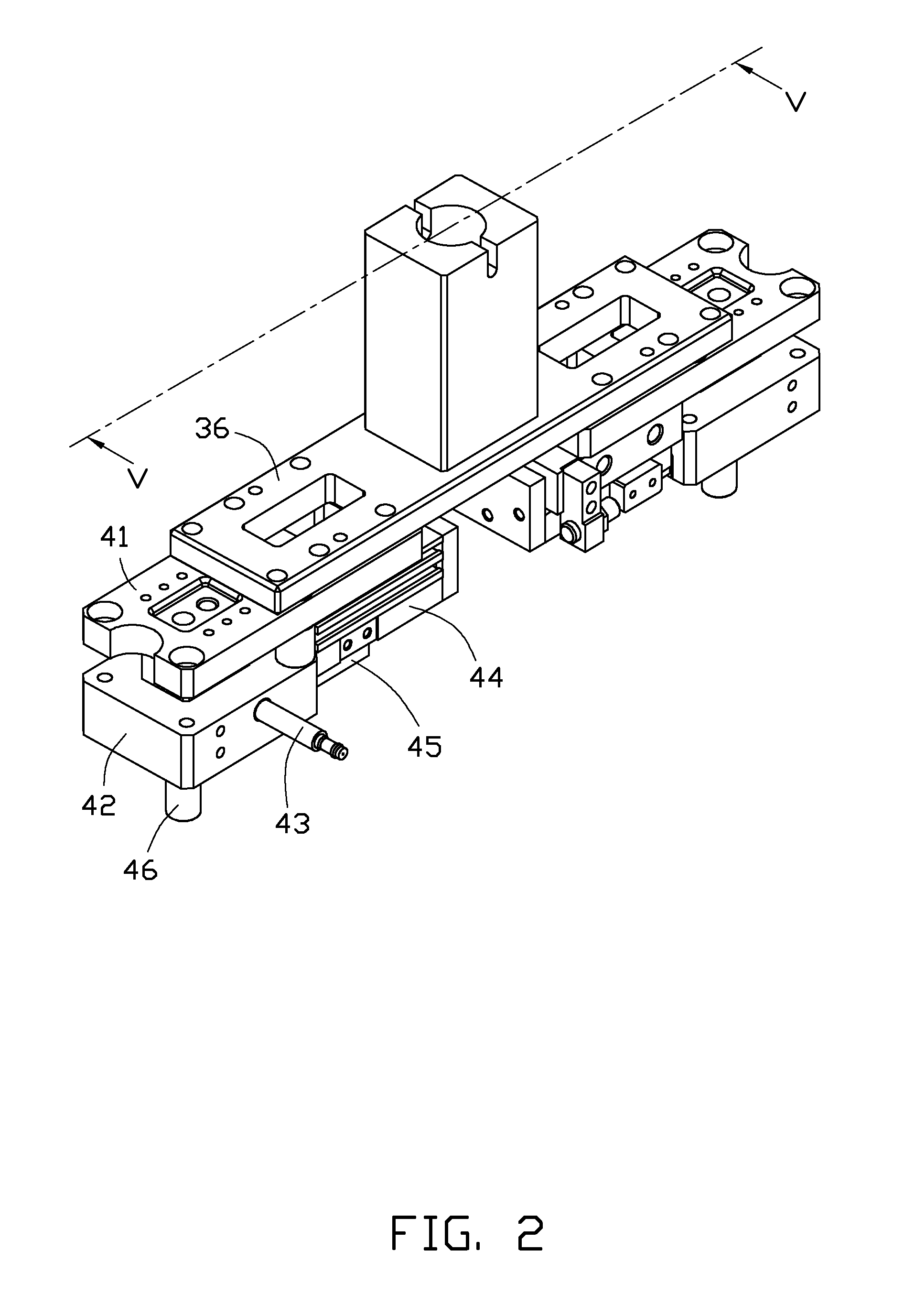
BACKGROUND[0001]1. Technical Field[0002]The present disclosure relates to a device for assembling workpieces, especially to a device for automatically assembling screws into a workpiece, such as an electronic device.[0003]2. Description of Related Art[0004]Housings of electronic devices, such as mobile phones, personal digital assistants (PDAs), and laptop computers need to be assembled with screws to secure components. The screws need to be screwed in predetermined positions of the housing in assembly. However, the screws are small in size, which makes them hard to hold and position manually. In addition, the amount of screws to be assembled is great, which costs a lot of time. Therefore, an automatic way of assembling the screws is very necessary.BRIEF DESCRIPTION OF THE DRAWINGS[0005]Many aspects of the disclosure can be better understood with reference to the following figures. The components in the figures are not necessarily drawn to scale, the emphasis instead being placed up...

Claims


Application Information

Patent Timeline
Patent Type & Authority Patents(United States)
IPC IPC(8): B23P19/00H05K13/02B23P19/06
CPCH05K13/02B23P19/001B23P19/06Y10T29/53265B23K37/00B23K37/0426
Inventor LIAO, GUO-SHENGDONG, CHENG-SHOULI, ZI-YANGWANG, GUANG-HONG
Owner SHENZHEN FUTAIHONG PRECISION IND CO LTD
Learn More