System and methods for video image processing

a video image and image processing technology, applied in the field of video images, can solve the problems of difficult manual adjustment of the zoom level of the video image, poor zoomed-in image quality, and insufficient system requirements, so as to increase the perceived quality of the detailed perspective display, reduce the perceived quality of the resulting display, and maximize the perceived quality

Active Publication Date: 2016-09-20
STC UNM
View PDF2 Cites 0 Cited by
  • Summary
  • Abstract
  • Description
  • Claims
  • Application Information

AI Technical Summary

Benefits of technology

[0024]An interpolation element is configured to increase the perceived quality of a portion of the video image. More specifically, an interpolation element may generate intermediate pixels that extend the resolution of the original video (as captured) to the displayed resolution so as to increase the perceived quality of the detailed perspective display.
[0026]A frame rate control element is configured to set the amount of video frames flashed per time period. For example, the frame rate of the panoramic precursor frames may be decreased to save resources, which may be spent increasing the perceived quality of the detailed precursor frames.
[0030]However, when enlarging the video image, the perceived quality of the resulting display may be decreased. Accordingly, in certain embodiments, the intermediate pixels are generated to extend the resolution of the original video image to the displayed resolution so as to increase the perceived quality of the detailed perspective display (a process called interpolation). A number of interpolation methods are available and, in certain embodiments, which interpolation method is applied may be automatically chosen by the system or may be chosen by the user via a user interface.
[0031]The system balances the frame rate of the detailed precursor frames—those that have been cropped, enlarged, and interpolated—and the panoramic precursor frames to maximize perceived quality for the detailed precursor frames while maintaining an acceptable video quality in the panoramic precursor frames. The video resolution for the detailed precursor frames may be increased and its frame rate is typically maintained at a higher rate (but less than the acquired frame-rate) than the frame rate for the panoramic precursor frames may be decreased. The basic goal is to shift computational resources from the non-detailed panoramic perspective display (where they are not needed as much since such action will not significantly reduce video quality) to the detailed perspective display.

Problems solved by technology

Clearly, such systems do not meet the need for simultaneously providing one close-up perspective and one wide-view perspective.
However, for certain functions, the user may be multi-tasking (e.g., manipulating surgical tools or taking notes while perceiving the video images of the target), which renders manually adjusting the zoom level of the video image challenging.
In addition, the quality of the zoomed-in image often is poor.
However, such two-camera systems may be cost-prohibitive, size-limiting if access to the target is restricted, or possibly detrimental to the observation if the second camera intensifies the observer effect.
Other attempts to provide video images split into two different perspective displays of a target have been unreliable, computationally expensive, or otherwise resulted in exceedingly low quality resolution of each perspective display.

Method used


Image

  • System and methods for video image processing
  • System and methods for video image processing
  • System and methods for video image processing

Examples


Embodiment Construction

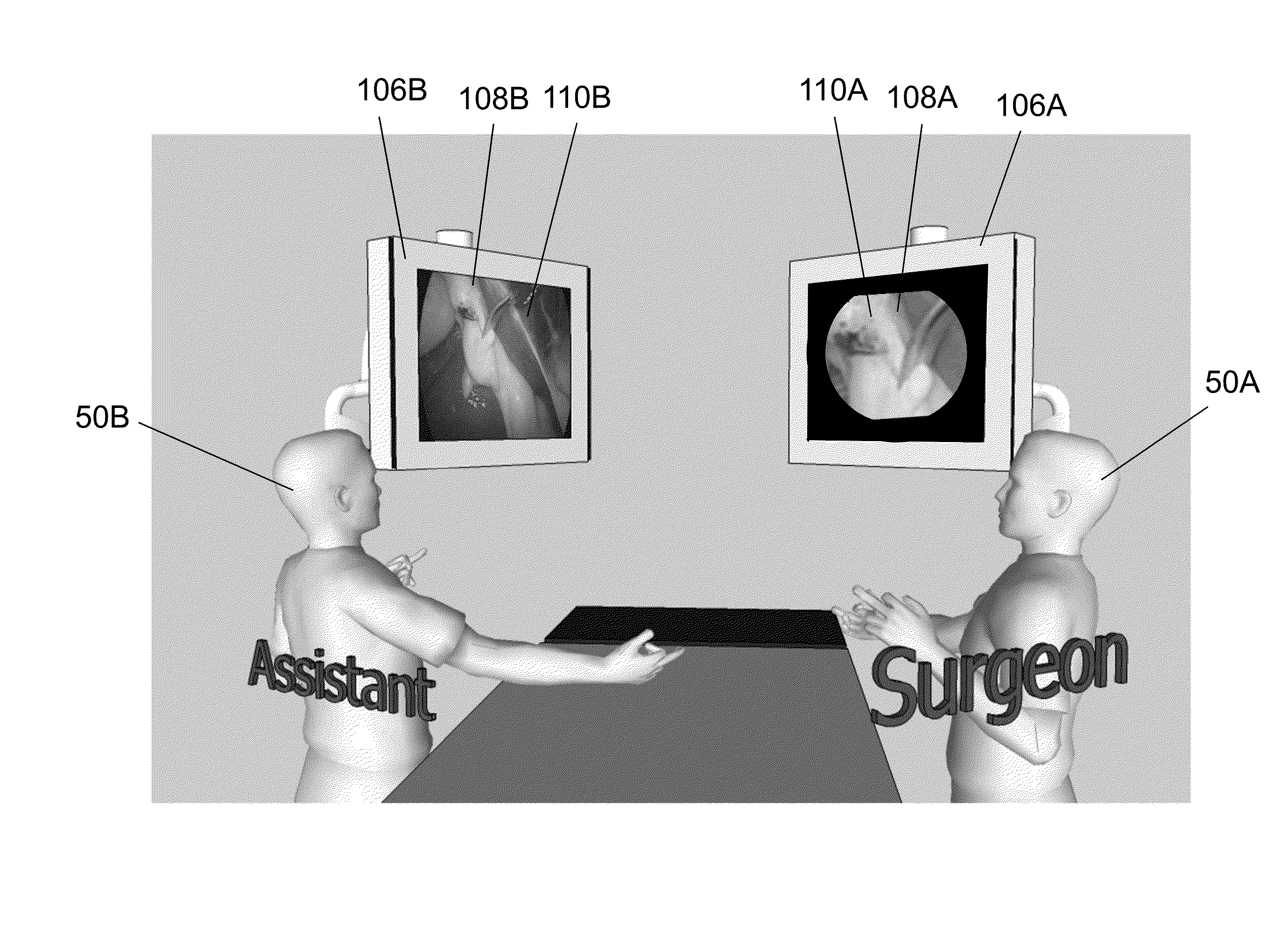
[0053]For purposes of this application, the present invention is discussed in reference to systems and methods of video image processing configured for use during minimally invasive surgeries, but the discussion is merely exemplary. The present invention is applicable to any function for which a single camera source component providing two different high resolution perspective displays of a target is useful.

[0054]Minimally invasive surgery may include various benefits such as reduced post-operative discomfort, reduced chance of infection, quicker recovery times, shorter hospital stays, quicker return to full activity, smaller external scars, and less internal scarring. Accurate and precise manipulation of surgical tools or instruments is desired during any surgical procedure, but this is particularly true with minimally invasive surgery.

[0055]Laparoscopic surgery is one type of minimally invasive surgery performed through small incisions. During laparoscopic surgeries, the health ca...


PUM


Abstract

Certain embodiments of the present invention include a system and methods for providing a video image display technology with separate video perspective displays. Each perspective display may be tailored and adapted in real-time to the differing roles of each user, e.g., one or more medical professionals of a surgical team. As an example, one video perspective display may be a panoramic perspective display for a primary surgeon and a second video perspective may be a detailed perspective display for the surgical assistant.

Description

CROSS REFERENCE TO RELATED PATENTS[0001]This application claims the benefit of U.S. Provisional Application No. 61 / 825,183 filed May 20, 2013, which is incorporated by reference herein in its entirety.FIELD OF THE INVENTION[0002]The invention relates generally to displaying video images from a single source.BACKGROUND OF THE INVENTION[0003]Video imaging technology permits capturing and displaying images of a target, possibly via an input / output interface such as an output component. Examples of an output component include a screen, monitor, touchscreen, speaker, light-emitting diode display, or projector and / or receiving element for projector (including, e.g., a wall projector, overhead projector, or head-mounted projector such as a Google Glass® unit).[0004]Such video imaging technology has many applications. For example, video imaging may be used for security functions (e.g., video surveillance of residences, commercial locations, warehouses, valuable objects, or other objects or ...

Claims


Application Information

Patent Timeline
Patent Type & Authority Patents(United States)
IPC IPC(8): H04N5/00G06T3/40H04N5/232
CPCH04N5/23238G06T3/4007H04N23/698
Inventor PEREZ, TIMOTHY WILLIAMPATTICHIS, MARIOS STEPHANOUJIANG, YUEBING
Owner STC UNM
Why Eureka
Try Eureka