Back pressure regulator with floating seal support

a back pressure regulator and floating seal technology, applied in the direction of diaphragm valves, fluid pressure control, instruments, etc., can solve the problems of real limitations on the low-pressure end of the diaphragm, and affecting the accuracy of the diaphragm

Active Publication Date: 2016-09-20
EQUILIBAR
View PDF13 Cites 8 Cited by
  • Summary
  • Abstract
  • Description
  • Claims
  • Application Information

AI Technical Summary

Problems solved by technology

However, for many applications where a significant gas flow is undesirable or cannot be assured, a BPR with true zero-flow capability is required.
This indentation of the PTFE, while useful in obtaining zero flow at higher pressures, also has real limitations on its low-pressure end and also contributes to imprecision and deadband.
Though the MITY MITE design serves as a type of industry standard, there are several other disadvantages, including sealing failures after thermal cycling.
While this approach offers potential for low flow performance due to the soft elastomeric seal, this is a very mechanically stressful environment for the soft O-ring to survive.
If the O-ring is fully supported by an inner wall of 80% to 85% of its height (as a standard static O-ring groove is), there can be problems achieving a true zero flow seal due to interference between the diaphragm and the hard inner wall.
If an inner support is shortened to avoid interference between the support and the diaphragm, the result can be either a failure to flow or a failure to fully close.
In summary, it is practically difficult to identify a support wall height which will reliably contain the O-ring at a variety of pressures without becoming blocked by the O-ring being extruded above the support wall.
Even when an O-ring and groove geometry is identified which appears to function through a wide range of pressures with a limited range of gas flow rates, the flow performance becomes unreliable when a higher flow rate of gas further stresses the O-ring.

Method used


Image

  • Back pressure regulator with floating seal support
  • Back pressure regulator with floating seal support
  • Back pressure regulator with floating seal support

Examples


Embodiment Construction

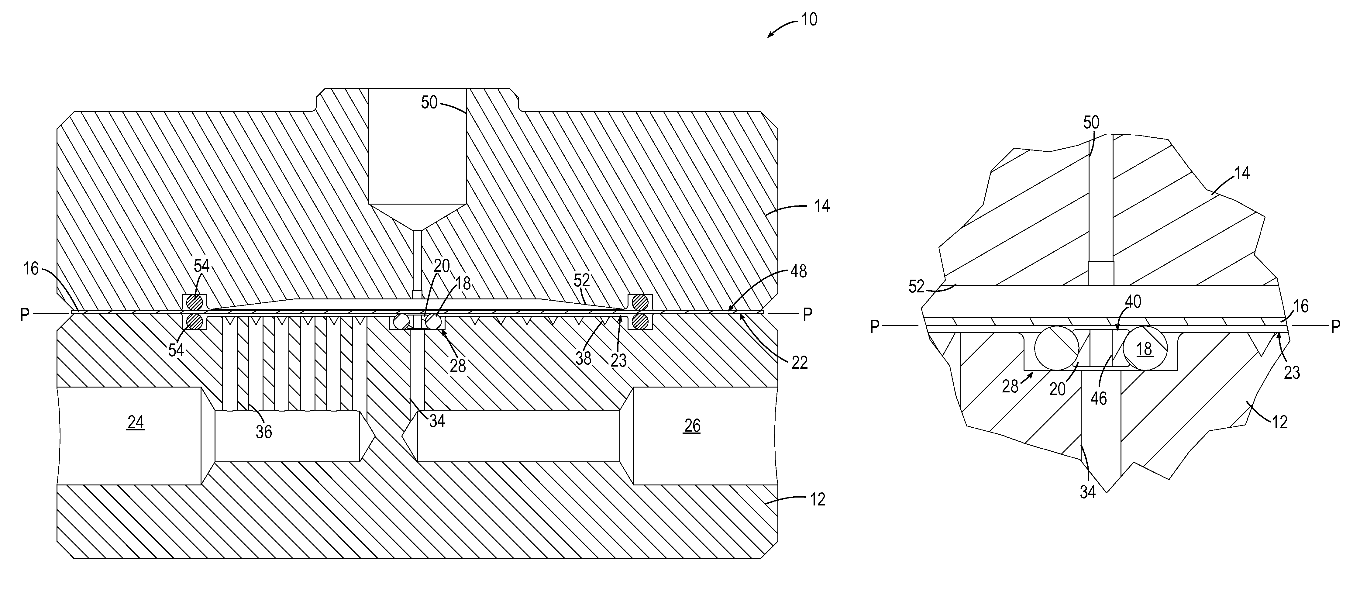
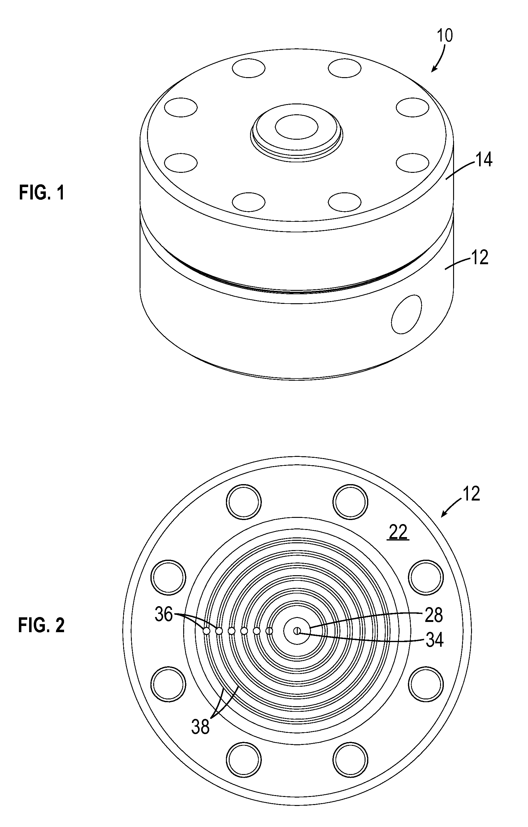
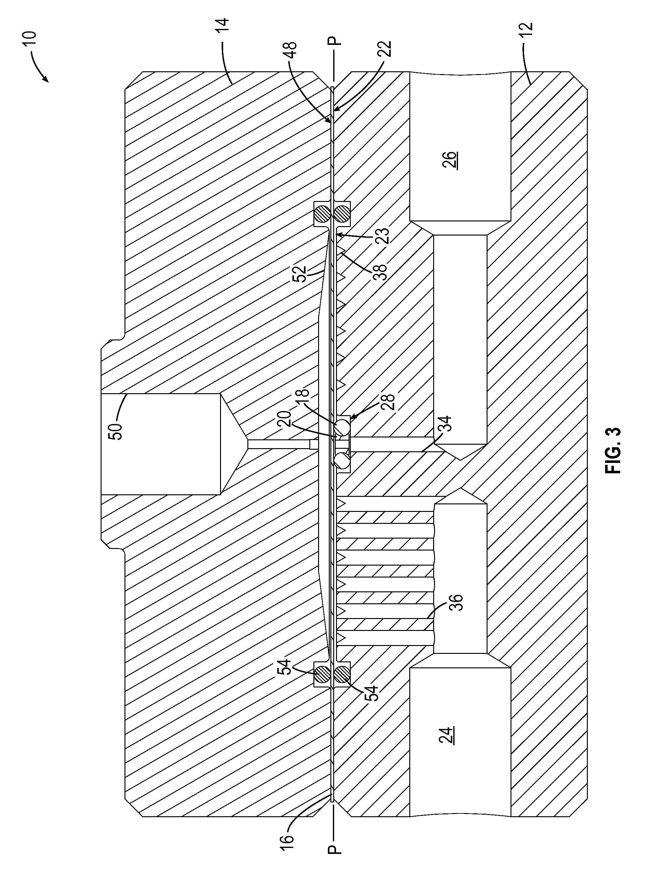
[0026]Referring to the drawings wherein identical reference numerals denote the same elements throughout the various views, FIGS. 1-3 depict an exemplary back pressure regulator 10 constructed according to an aspect of the present invention.

[0027]For purposes of explanation, it is noted that “back pressure regulator” and “relief valve” are two similar terms which describe the same functional device, though with different operational emphases. For relief valves, the emphasis is on the off / on flow interface, with expectations of zero flow through the device up to some predetermined set pressure, and maximum flow above the set pressure. For back pressure regulators, the emphasis is often on steady state flow control over a defined flow rate window, with less emphasis on the off / on flow threshold. It is noted that the back pressure regulator 10 described herein is suitable for use with gases, liquids, or two-phase systems.

[0028]The back pressure regulator 10 includes a body 12 and a ref...


PUM


Abstract

A sealing apparatus for a back pressure regulator includes: a body defining a process surface, and including: at least one process void communicating with the process surface; a recess disposed in the process surface; a floating support hub disposed in the recess, carrying an O-ring; a vent void communicating with the recess; an inlet port disposed in fluid communication with the at least one process void and adapted to be coupled in fluid communication with a fluid at a process pressure; and an outlet port disposed in fluid communication with the vent void; and a diaphragm having opposed reference and process sides, the diaphragm disposed against the body such that the process side is substantially coplanar with the process surface.

Description

BACKGROUND OF THE INVENTION[0001]The present invention relates to pressure regulation, and more particularly to a diaphragm-type valve which controls a process pressure to match a reference pressure signal.[0002]Dome loaded back pressure regulators (BPR) are used in many applications, including many research reactors and gas analytical applications in laboratory environments. A typical laboratory example would be core analysis, which uses a heated reactor containing an earthen core sample. Hydrocarbon products are condensed from the gaseous outflow of the reactor as part of the analysis. A back pressure regulator is typically used to simulate various overburden pressures in the earth, and is installed downstream of the reactor. Typical pressure ranges for these applications is between 340 kPa and 21 MPa (50 psig and 3000 psig)[0003]If an inert gas stream is introduced into the reactor, one of several designs of small back pressure regulators can be used to control the sample pressur...

Claims


Application Information

Patent Timeline
Patent Type & Authority Patents(United States)
IPC IPC(8): F16K7/17G05D16/06G05D16/18F16K1/42F16K7/16F16K7/12F16K31/165
CPCF16K7/17G05D16/063G05D16/0638G05D16/0655G05D16/185F16K1/42F16K7/126F16K7/16F16K31/165G05D16/0658G05D16/024
Inventor JENNINGS, JEFFREY DEANTANG, TONY BOYDROBERTS, KEITH ALAN
Owner EQUILIBAR
Why Eureka
Try Eureka