Tie rod assembly with integrated safety tip

Inactive Publication Date: 2016-09-13
SPARR CHRISTOPHER E
View PDF12 Cites 1 Cited by
  • Summary
  • Abstract
  • Description
  • Claims
  • Application Information

AI Technical Summary

Benefits of technology

This patent is about a new design of a tie rod end that has a safety feature that prevents the tie rod end from separating completely. This safety feature is a disc that is part of the inner mounting stud of the tie rod end. The safety disc catches the tie rod housing and prevents it from separating from the mounting stud of the tie rod end. The new design is sealed to prevent contamination and can be greased using a normal grease gun. The purpose of this design is to prevent loss of steering in the event of a tie rod end joint failure.

Problems solved by technology

The improved design adds a safety feature that will not allow complete tie rod end joint separation, greatly reducing the potential of loss of steering in the event of tie rod end joint failure.
The safety disc has a larger outside diameter than the inner diameter of the tie rod end housing, which allows the safety disc to catch the tie rod housing and not allow it to separate completely from the mounting stud of the tie rod end.

Method used


Image

  • Tie rod assembly with integrated safety tip
  • Tie rod assembly with integrated safety tip
  • Tie rod assembly with integrated safety tip

Examples


Embodiment Construction

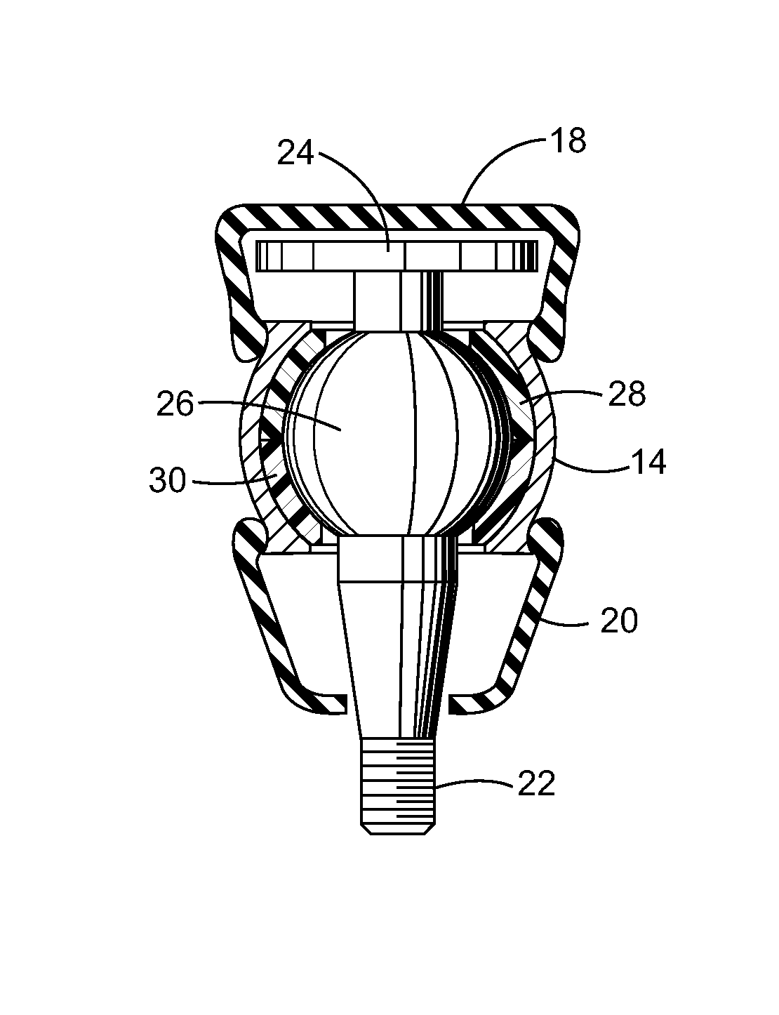
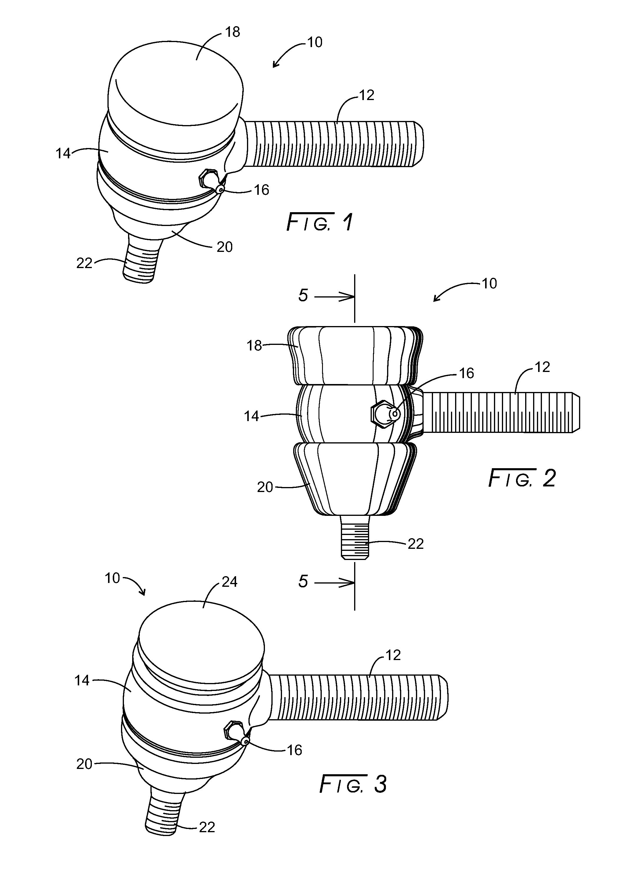
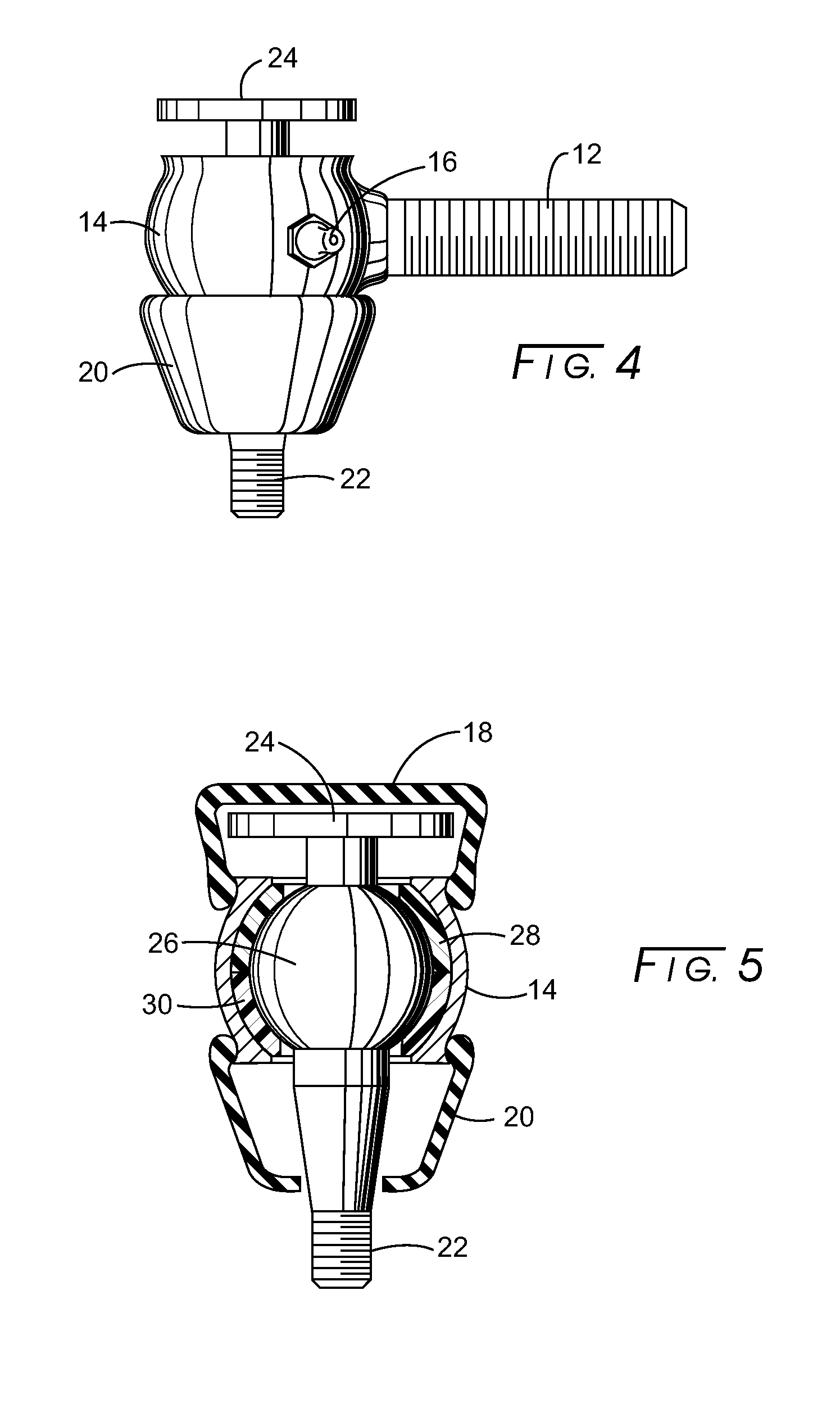
[0013]Referring initially to FIGS. 1 and 2, a tie rod assembly, 10, has a tie rod, 12, extending outward from tie road assembly 10. The proximal end of tie rod 12 is threaded. The distal end of tie rod 12 is formed into a body, 14, having spherically expanded interior that is substantially empty. The body has a truncated top and a truncated bottom. Both the truncated body top and truncated bottom of body 14 have a hole penetrating therethrough. The holes are in alignment transverse to the longitudinal extent of tie rod 12. Such holes are composed of an aperture located at the top truncated surface of body 14 and an aperture located at the lower truncated surface of body 14. A grease port, 16, extends outwardly from body 14 and communicates with the spherically expanded interior of body 14 for lubrication purposes.

[0014]The upper and lower edges of body 14 are rolled to form a lip. Sealing the spherically expanded interior of body 14 are an upper flexible cover 18 and a lower flexibl...


PUM


Abstract

Disclosed is a tie rod having a threaded shaft at a proximal end and a body at a distal end. The body has a spherically expanded, substantially empty interior and having a truncated top and a truncated bottom. Each truncated top and bottom having a hole wherein the holes are in alignment transverse to the longitudinal extent of the tie rod. A tie rod pin has a distal end that extends through the truncated bottom body hole and terminated with a threaded distal end, an intermediate spherical section movably nested within the spherically expanded truncated tie rod body, and a distal end that extends from the spherical section through the truncated top body hole and being terminated with a plate being larger in diameter than the hole that penetrates the upper truncated body so that the tie rod pin is restrained from pulling through the tie rod body.

Description

CROSS-REFERENCE TO RELATED APPLICATIONS[0001]None.STATEMENT REGARDING FEDERALLY SPONSORED RESEARCH[0002]Not applicable.BACKGROUND[0003]The present disclosure relates to traditional automotive tie rods and more particularly to a design that restrains the tie rod ends from becoming dislodged from their housing. A common issue that is seen with traditional tie rod ends is joint separation, which occurs when the tie rod end housing separates from the inner stud of the tie rod end. Such separation allows the tie rod to fall free from the axle spindle, which will cause loss of steering control to the wheel to which it was attached.BRIEF SUMMARY[0004]The improved design adds a safety feature that will not allow complete tie rod end joint separation, greatly reducing the potential of loss of steering in the event of tie rod end joint failure. The improved tie rod end has an integrated safety feature of a disc that is part of the inner mounting stud of the tie rod end that extends through th...

Claims


Application Information

Patent Timeline
IPC IPC(8): B62D7/16B62D7/20
CPCB62D7/20B62D7/166F16C11/0666F16C11/0614F16C17/24
Inventor SPARR, CHRISTOPHER E.
Owner SPARR CHRISTOPHER E
Why Eureka
Try Eureka