
Inner type tracheostomy tube

a tracheostomy tube, inner type technology, applied in the direction of tracheal tubes, life-saving devices, respiratory apparatus, etc., can solve the problems of unsafe use and danger in use, and achieve the effect of easy and safe chang

Active Publication Date: 2016-09-06
VITALTEC CORP
View PDF16 Cites 2 Cited by
  • Summary
  • Abstract
  • Description
  • Claims
  • Application Information

AI Technical Summary

Benefits of technology

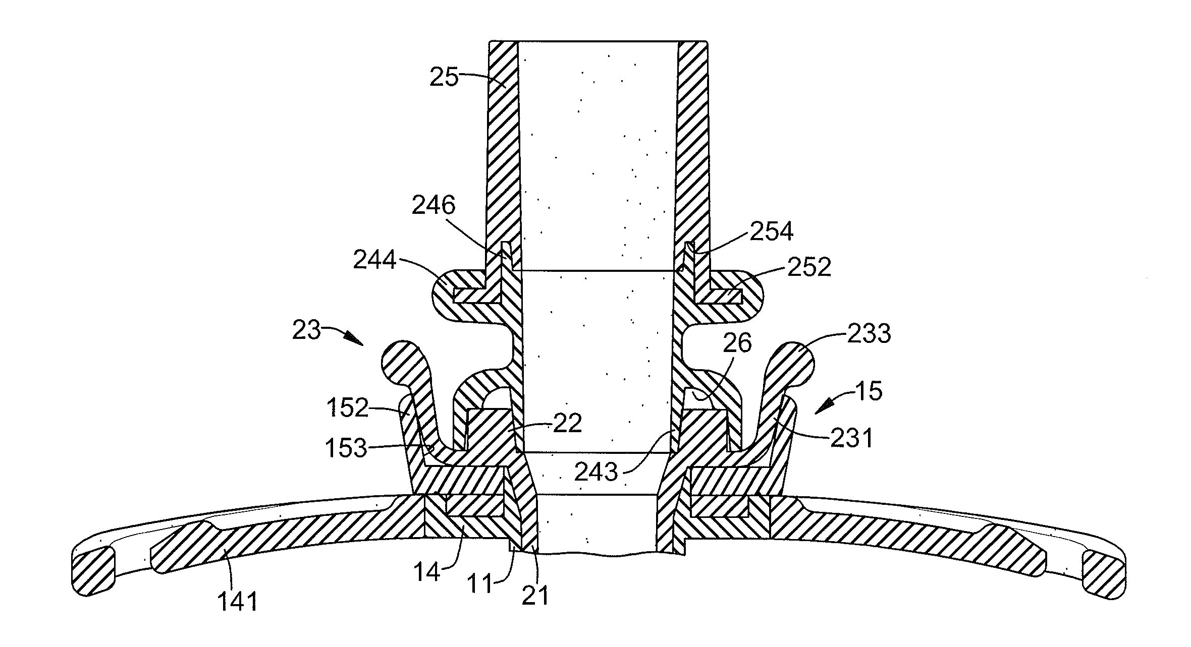
[0009]The main objective of the present invention is to provide an inner type tracheostomy tube that can easily and safely change an inner cannula of the inner type tracheostomy tube.

Problems solved by technology

However, the inner cannula of the conventional inner type tracheostomy tube is screwed with the outer tube and may be separated from the outer tube when the inner cannula is rotated with a respiratory tub, and this is dangerous in use.
Furthermore, when the inner cannula of the conventional inner type tracheostomy tube is connected to the outer tube by an exerted clamping structure, dirt may be accumulated on the exerted clamping structure causing infection.
In addition, the patent may knock the exerted clamping structure of the inner cannula to cause the inner cannula to separate from the outer tub, and this is unsafe in use.

Method used


Image

  • Inner type tracheostomy tube
  • Inner type tracheostomy tube
  • Inner type tracheostomy tube

Examples


Embodiment Construction

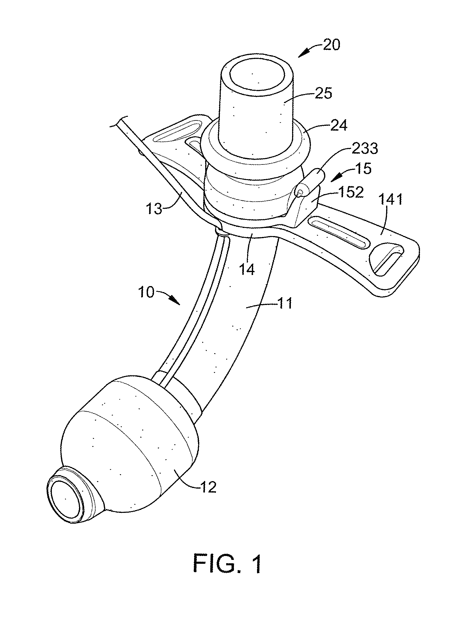
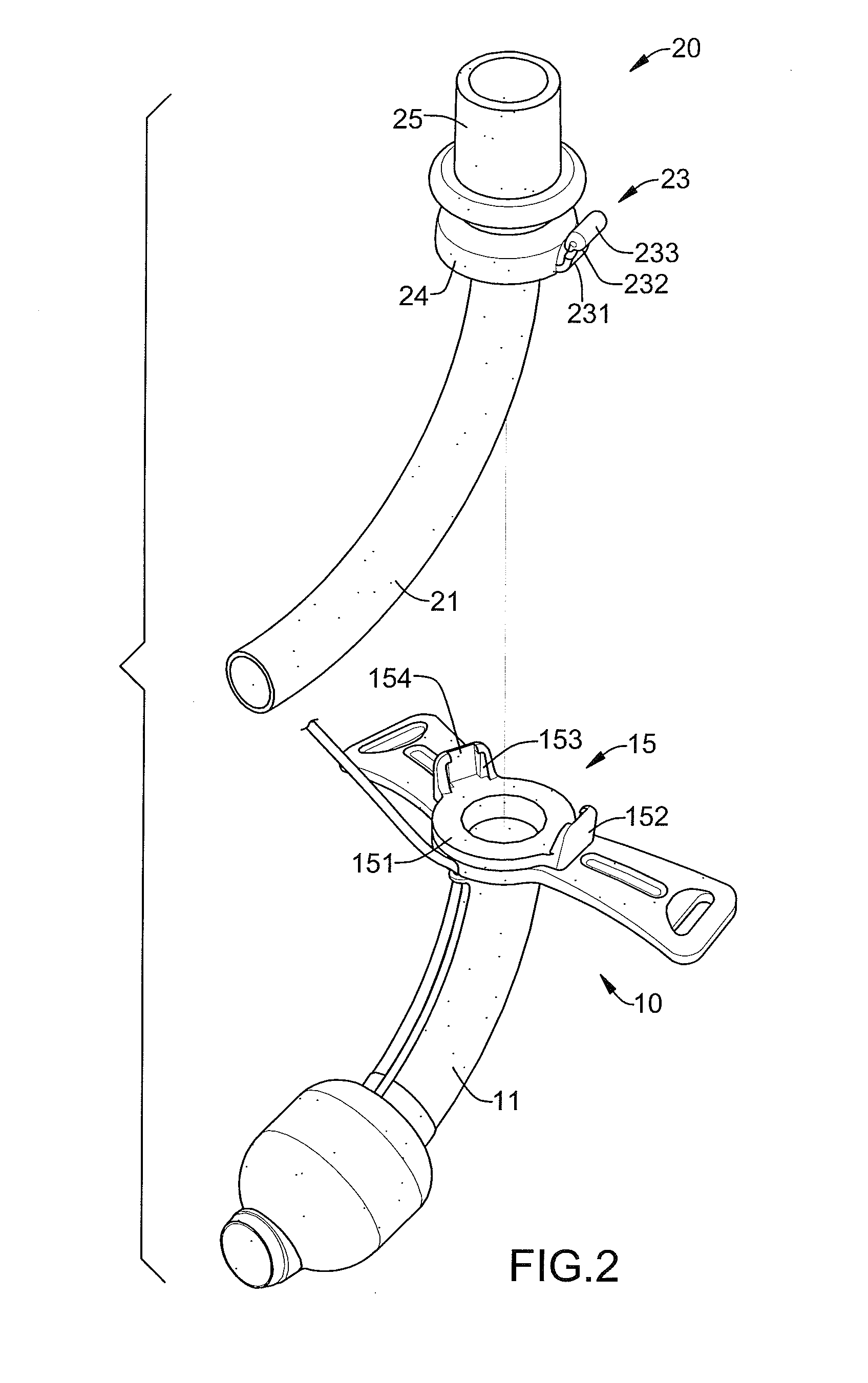
[0019]With reference to FIGS. 1 to 5, an inner type tracheostomy tube in accordance with the present invention has an outer tube 10 and an inner cannula 20.

[0020]The outer tube 10 has an airway tube 11, an inflatable cuff 12, an inflating tube 13, a neck mount 14 and a holding mount 15.

[0021]The airway tube 11 may be a hard tube and has an inner end, an outer end and an external surface. The inflatable cuff 12 is mounted around the external surface near the inner end of the airway tube 11, is inflated to form a seal in a patient's neck for mechanical breathing, and is totally deflated when the outer tube 10 is inserted into or withdrawn from the patient's trachea. The inflating tube 13 is connected to and communicates with the inflatable cuff 12 to inflate or deflate the inflatable cuff 12.

[0022]The neck mount 14 may be an annular hard board, is securely mounted around the external surface of the airway tube 11 near the outer end of the airway tube 11 and has a top, two sides and tw...


PUM


Abstract

An inner type tracheostomy tube has an outer tube and an inner cannula. The outer tube has an airway tube, an inflatable cuff and an inflating tube. The inner cannula is connected to the outer tube and has an inner tube, a disk segment, a connecting mount and a connector. The connecting mount is soft and bendable, is securely mounted around the disk segment and has a bottom end, a top end and a flange coat. The bottom end is securely mounted around the disk segment and has an inner surface and an air gap formed between the inner surface of the bottom end of the connecting mount and the disk segment. The connector is securely mounted around the top end of the connecting mount and has a bottom end and a flange formed around the bottom end of the connector and enclosed by the flange coat.

Description

[0001]The present invention is a continuation-in-part of application Ser. No. 12 / 899,624, filed on Oct. 7, 2010, now abandoned.BACKGROUND OF THE INVENTION[0002]1. Field of the Invention[0003]The present invention relates to an inner type tracheostomy tube and, more particularly, to an inner type tracheostomy tube that can easily and safely change an inner cannula of the inner type tracheostomy tube.[0004]2. Description of Related Art[0005]A patient who has dyspnea due to trachea obstruction or disease caused by weakness or drug effects may require a conventional tracheostomy tube inserted into the trachea through a stoma formed through the trachea to provide air from a respiratory tube directly to the patient through the conventional tracheostomy tube.[0006]When changing the conventional tracheostomy tube, a surgical operation is needed to inconveniently operate on the patient under a general anesthesia. A conventional inner type tracheostomy tube can be used to improve the aforemen...

Claims


Application Information

Patent Timeline
Patent Type & Authority Patents(United States)
IPC IPC(8): A61M16/00A62B9/02A61M16/04
CPCA61M16/0488A61M16/0427A61M16/0465A61M16/0497A61M16/0434
Inventor CHANG, TI-LICHIU, SHENG-YU
Owner VITALTEC CORP
Learn More