
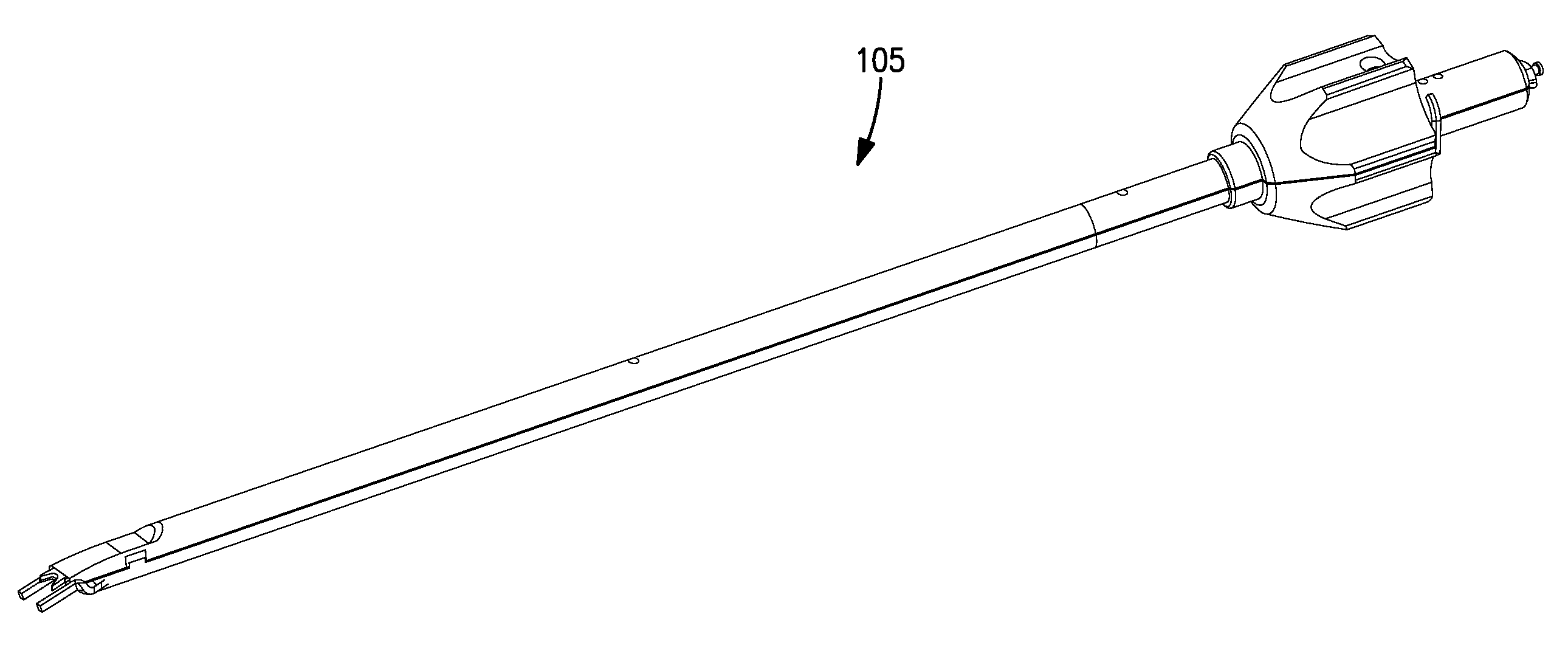
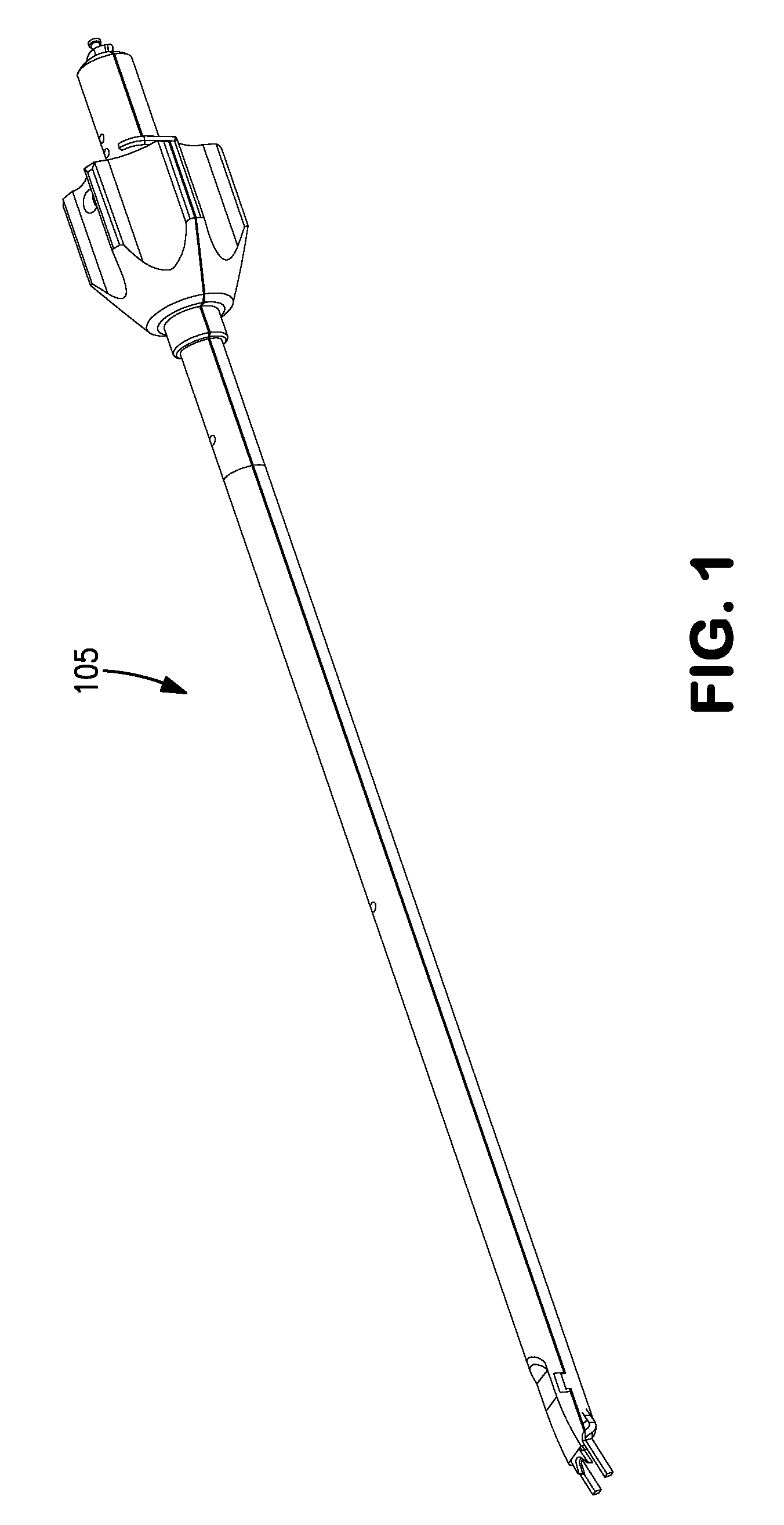
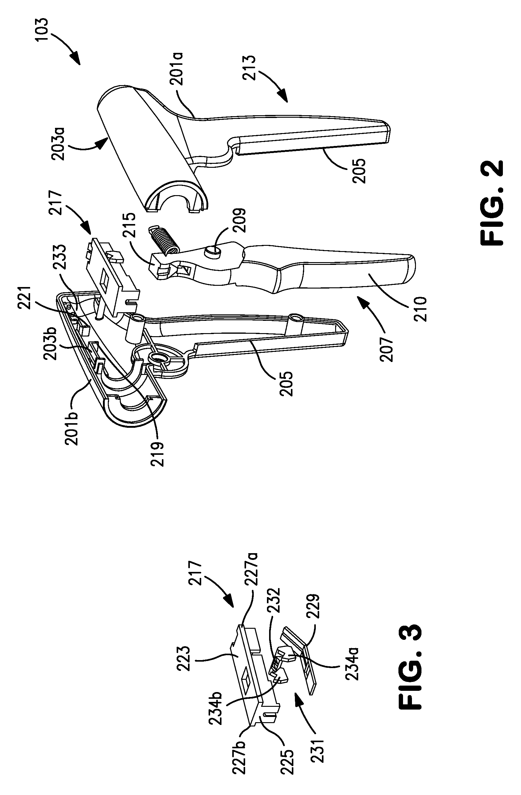
Surgical clip applicator

a clip applicator and clip technology, applied in the direction of wound clamps, etc., can solve the problems of vessel slippage and other problems, and achieve the effects of convenient and reliable clip application, reduced or avoided problems, and more predictable and reliabl

Active Publication Date: 2016-09-06
DESIGN STANDARDS CORP
View PDF39 Cites 54 Cited by
  • Summary
  • Abstract
  • Description
  • Claims
  • Application Information

AI Technical Summary

Benefits of technology

The invention provides a disposable clip applicator that can be easily inserted into a disposable or non-disposable handle and discarded after using all the clips. The mechanism is simple and reliable, and the applicator can be reused or discarded while the handle can be re-used with other clips. This design reduces the likelihood of dropped or misapplied clips, making it convenient and reliable to apply clips as desired.

Problems solved by technology

Otherwise, the U-shaped clip may have gaps when closed, allowing leakage, or may become V-shaped and allow vessel slippage.
However, slippage of the vessel remains a problem.

Method used


Image

  • Surgical clip applicator
  • Surgical clip applicator
  • Surgical clip applicator

Examples


Embodiment Construction

[0027]Embodiments of the invention will be described with reference to the accompanying drawing figures wherein like numbers represent like elements throughout. Before embodiments of the invention are explained in detail, it is to be understood that the invention is not limited in its application to the details of the examples set forth in the following description or illustrated in the figures. The invention is capable of other embodiments and of being practiced or carried out in a variety of applications and in various ways. Also, it is to be understood that the phraseology and terminology used herein is for the purpose of description and should not be regarded as limiting. The use of “including,”“comprising,” or “having,” and variations thereof herein is meant to encompass the items listed thereafter and equivalents thereof as well as additional items. The terms “mounted,”“connected,” and “coupled,” are used broadly and encompass both direct and indirect mounting, connecting, and...


PUM


Abstract

A surgical clip applicator includes a handle configured to produce translational movement; a cartridge containing a plurality of clips arranged in a row, the cartridge including a jaw assembly for receiving and closing a clip; a jaw closing mechanism for closing the jaw assembly; a clip feed mechanism for serially feeding a lead clip from the row to the jaw assembly; a clip advance mechanism for advancing the row as the lead clip is fed to the jaws; and a rocker mechanism for translating translational movement from the handle opposite translational movement of the haw closing mechanism in one direction and the clip feed mechanism and clip advance mechanism in an opposite direction.

Description

CROSS REFERENCE TO RELATED APPLICATION[0001]This application is a non-provisional application of U.S. application Ser. No. 61 / 805,511, filed Mar. 26, 2013, which is incorporated herein by reference in its entirety.BACKGROUND OF THE INVENTION[0002]The invention relates generally to devices that apply surgical or ligating clips. More specifically, the invention relates to a device that rapidly deploys clips at a surgical site.[0003]There are many different designs for surgical clip applicators for a variety of surgical procedures. Several types of surgical clips are known for ligating vessels and ducts. One type of surgical clip employs a generally U-shaped configuration. However, a kink forms in the bend of such a clip during closing, and the position of the kink must be carefully controlled to maintain the relative position and closure of the legs. Otherwise, the U-shaped clip may have gaps when closed, allowing leakage, or may become V-shaped and allow vessel slippage.[0004]The U-s...

Claims


Application Information

Patent Timeline
Patent Type & Authority Patents(United States)
IPC IPC(8): A61B17/128
CPCA61B17/1285
Inventor CRAINICH, LAWRENCETRABKA, JOSEPHGILCHREST, MAURICECARIGNAN, THOMAS
Owner DESIGN STANDARDS CORP
Learn More