
System for storing energy by means of compressed air

a technology of compressed air and energy storage, which is applied in the direction of machines/engines, mechanical equipment, greenhouse gas reduction, etc., can solve the problems of uneconomical initial investment of many millions of euros for a bore into the ground, and the cost of the operation of such a plant is almost exclusively capital cos

Active Publication Date: 2016-08-02
FRAUNHOFER GESELLSCHAFT ZUR FOERDERUNG DER ANGEWANDTEN FORSCHUNG EV
View PDF13 Cites 4 Cited by
  • Summary
  • Abstract
  • Description
  • Claims
  • Application Information

AI Technical Summary

Benefits of technology

The patent text describes a method to solve the problem of uneven availability of renewable energy by using compressed-air storage. To make this method more effective, it needs to be cheaper and allow for longer periods of storage capacity that can be partially utilized. A new approach is needed to overcome the challenges associated with fluctuating pressure and limited storage capacity. The use of the same radial turbomachine for both pumping and turbine operation can help to lower costs and improve efficiency.

Problems solved by technology

In the field of electricity supply, difficulties are posed by the fact that the availability of renewable energy, such as wind—utilized by means of wind turbines—and sun—utilized by means of photovoltaics—fluctuates greatly and the demand for electrical energy can be substantially covered by renewable energy only if the electricity generated thereby can be stored.
Known methods for this are storage batteries—presently too expensive—pumped-storage power plants—these require relatively large height differences and do not exist for example in the North German lowlands, and furthermore often elicit public protests owing to “landscape degradation”—or compressed-air storage plans (often referred to in the literature as CAES—“Compressed Air Energy Storage”).
The costs for the operation of such a plant are almost exclusively capital costs.
The same problem is encountered if it is sought to construct small stores in which the expensive initial investment of many millions of Euros for a bore into the ground is uneconomical, and which are thus dependent on small overground stores.
Here, too, the capital costs of the plant per stored kWh of capacity are lower the higher the pressure and the higher the pressure fluctuations in the store are.
If an underground storage volume is filled sometimes to a greater extent and sometimes to a lesser extent, then one encounters a fluctuating pressure therein (considerations have been made regarding pressure compensation using water, described for example in DE102007042837A1 and also in many earlier sources, but this was not realized owing to the difficulties associated with the water) and in the turbomachines that compress or expand compressed air, the flow conditions deviate from the design point, resulting in losses in efficiency.
Therefore, the pressure fluctuations are limited to low values, the storage capacity of the volume is thus only partially utilized, more volume is thus required, and costs are higher.
In the cited DE102007042837A1, it is the intention for a high-pressure compressor designed specifically for fluctuating pressure to eliminate the problem using precisely such a turbine; another approach would be rotational speed regulation of the turbomachines in order, similarly to the approach with pump turbines of regulable rotational speed in pumped-storage power plants, to keep the velocity triangles approximately congruent and thus efficiency losses low—said approach then however has the disadvantage of the costs for cumbersome power electronics in the megawatt range and can only with difficulty provide the demand for so-called short-circuit current, as demanded in conventional electricity grids.
In a solution with only turbomachines, it is also difficult to realize high pressures for the good utilization of the storage volume, in particular in the case of less than 50 megawatt plant power.
Owing to the high temperature fluctuations, there is a relatively long time between standstill and running at full load.

Method used


Image

  • System for storing energy by means of compressed air
  • System for storing energy by means of compressed air
  • System for storing energy by means of compressed air

Examples


Embodiment Construction

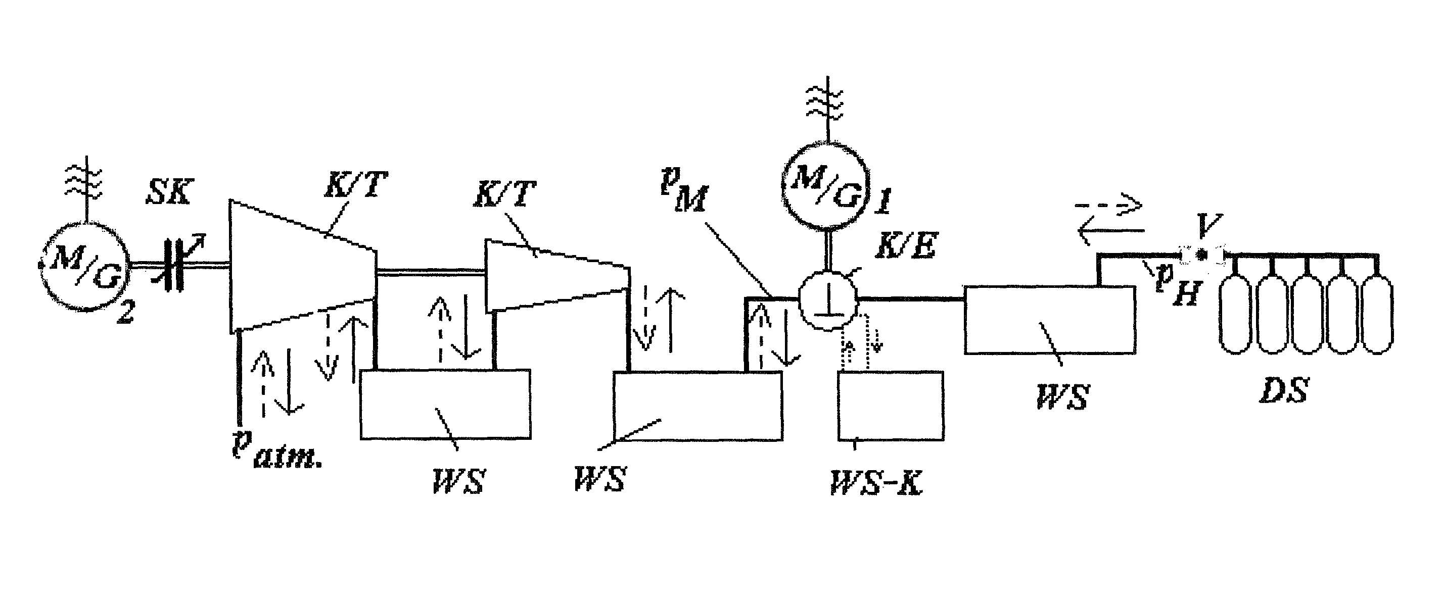
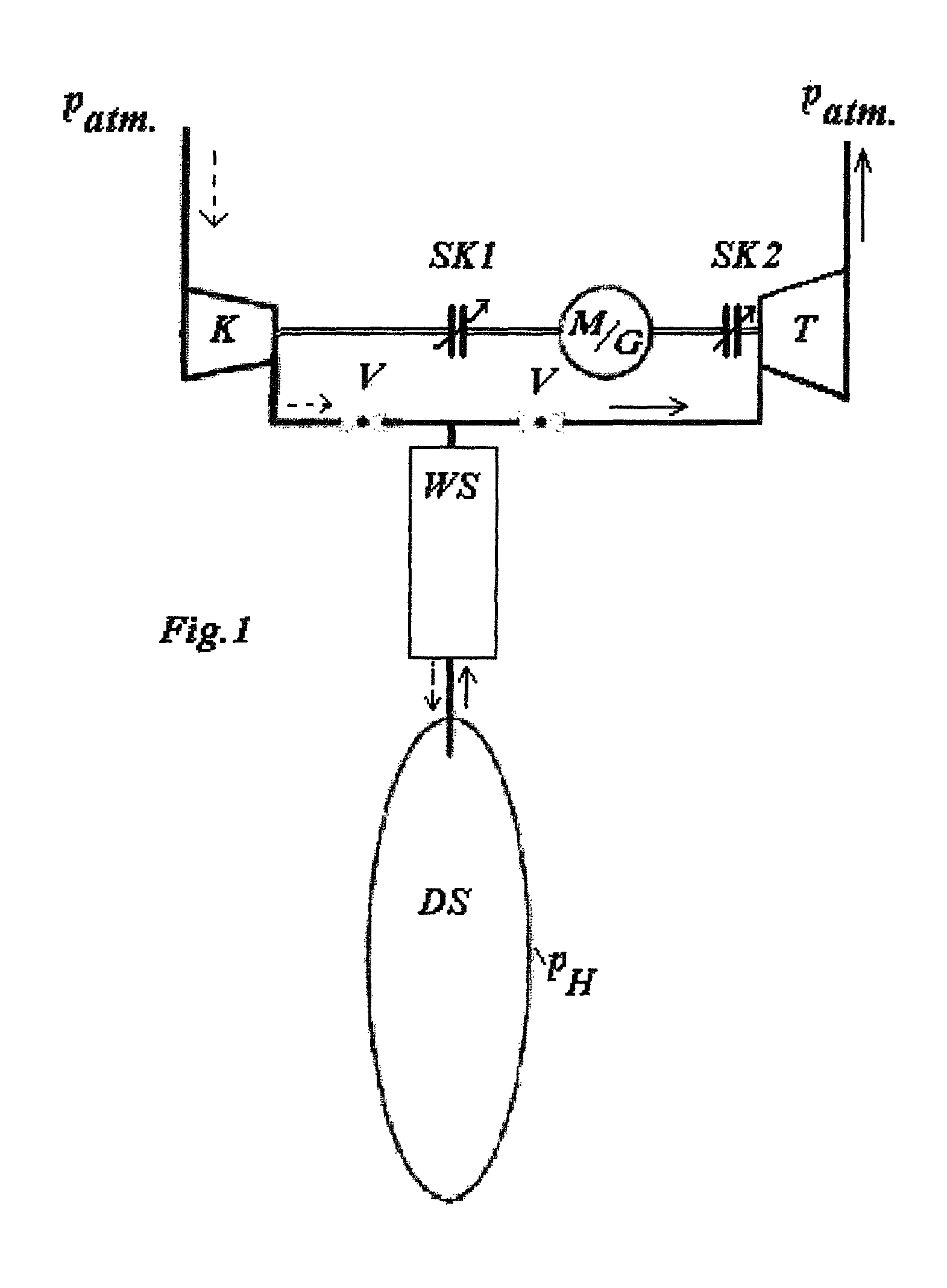
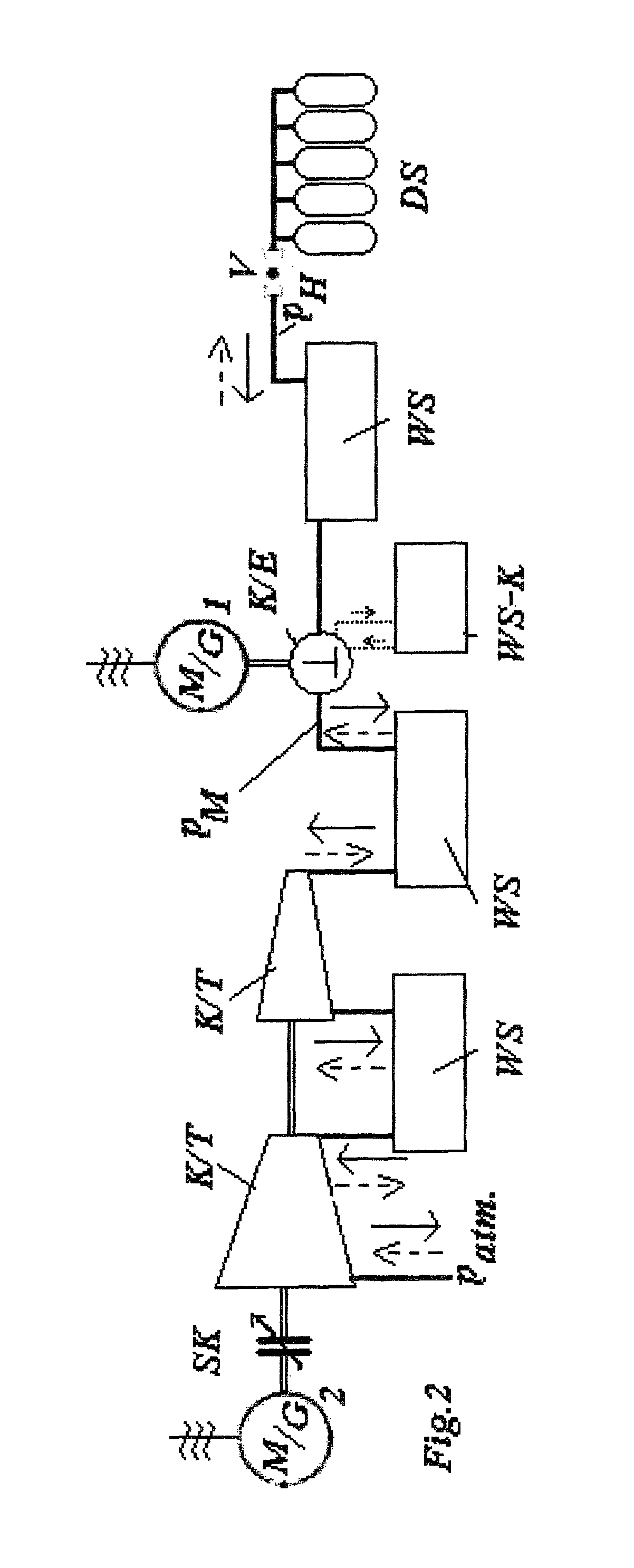
[0029]It is the intention for the possibility of storing energy, in particular renewable energy, on the medium scale of approximately 1000 to 100,000 kWh using compressed air to be improved through the creation of a specific combination of machines which alternately compresses ambient air for the storage of energy and re-expands said compressed air for removal from storage. The storage costs are thus defined substantially by the production costs of the storage volume. The costs are reduced through good utilization of the storage volume by means of high-pressure and high pressure fluctuation. This is possible by means of a combination of a high-pressure machine (preferably high-pressure positive-displacement machine), in particular with regulable control timing, connected in series with a low-pressure turbomachine, wherein both operate as a compressor during storage and as an expansion machine during removal from storage.

[0030]It is advantageously the case that a low-pressure turboma...


PUM


Abstract

A plant for storing energy by means of compressed air, in which: a storage volume accommodates air at elevated pressure pH; for energy storage, ambient air is compressed and introduced into the storage volume; for removal from storage, compressed air is extracted from the storage volume and discharged into the environment, performing work; at least one low-pressure turbomachine for alternate compression and expansion respectively compresses ambient air to a medium pressure pM and expands said ambient air from said pressure; at least one high-pressure machine for alternate compression and expansion respectively compresses air from the medium pressure pM to the store pressure pH and expands said air from the latter pressure; and said low-pressure turbomachine and high-pressure machine are connected in series in terms of flow and are mechanically coupled to in each case one, or to one common, electric machine that operates selectively as a motor and generator.

Description

STATEMENT OF RELATED APPLICATIONS[0001]This patent application claims the benefit of International Patent Application No. PCT / EP2012 / 003704 having an International Filing Date of 5 Sep. 2012, which claims the benefit of German Patent Application No. DE102011112280.3 having a filing date of 5 Sep. 2011.BACKGROUND OF THE INVENTION[0002]1. Technical Field[0003]The invention relates to a plant for storing energy by means of compressed air.[0004]2. Prior Art[0005]Initial State:[0006]Fossil energy is to be replaced (owing to CO2) with renewable energy. In the field of electricity supply, difficulties are posed by the fact that the availability of renewable energy, such as wind—utilized by means of wind turbines—and sun—utilized by means of photovoltaics—fluctuates greatly and the demand for electrical energy can be substantially covered by renewable energy only if the electricity generated thereby can be stored. Known methods for this are storage batteries—presently too expensive—pumped-s...

Claims


Application Information

Patent Timeline
Patent Type & Authority Patents(United States)
IPC IPC(8): F15B1/02F02C1/10F02C6/16F02G1/043F02C1/02
CPCF02C6/16F02C1/02F02C1/10F02G1/043F15B1/024F03D9/17Y02E10/72Y02E60/15F03D9/255Y02E60/16Y02E70/30
Inventor DAMGEN, ULRICHMEIER-SCHEUVEN, WOLF D.
Owner FRAUNHOFER GESELLSCHAFT ZUR FOERDERUNG DER ANGEWANDTEN FORSCHUNG EV
Learn More