Belt buckle with release lock

a belt buckle and release lock technology, applied in the field of belt buckles, can solve the problem of the belt buckle opening automatically risk, and achieve the effect of convenient integration and inexpensive manufacturing

Active Publication Date: 2016-08-02
TRW AUTOMOTIVE GMBH
View PDF15 Cites 3 Cited by
  • Summary
  • Abstract
  • Description
  • Claims
  • Application Information

AI Technical Summary

Benefits of technology

[0006]It is the object of the invention to provide a belt buckle having a safety mechanism that is easy to integrate for preventing the belt buckle from automatically opening which works reliably and can be inexpensively manufactured.
[0009]The invention is based on the finding that inadvertent opening of a belt buckle can be prevented in that, upon occurrence of high acceleration of an inertia force acting on the release button in the actuating direction (first direction), a counterforce is automatically applied. According to the invention, the mass body and the coupling lever are provided for this purpose. The rotatable but not displaceable coupling lever ensures that the inertia force acting on the mass body is transmitted to the release button in the inverse direction. In this way the release button can be prevented from performing undesired displacement in the actuating direction. The safety mechanism according to the invention requires only few simple components so that a largely easy integration in a belt buckle without excessive extra costs is possible.
[0014]In order to ensure largely resistance-free deflection of the coupling lever while the release button is normally actuated, a design that enables the second free arm to slide onto the step of the release button upon deflection of the coupling lever is of advantage.
[0017]In the preferred embodiment of the latch mechanism the latter includes a swivel body that is pivoted about an axis of rotation at the mass body and has a center of gravity which is eccentric relative to its axis of rotation. The inertia force acting on the swivel body when the latter is accelerated generates a torque which results in deflection of the swivel body. This automatic deflection of the swivel body can be advantageously used to lock the mass body.
[0020]An alternative embodiment of the belt buckle according to the invention can do without a swivel body, which allows for a considerable reduction of the construction length of the belt buckle. In the alternative embodiment the latch mechanism is designed so that a movement of the mass body in the second direction causes a rotation of the coupling lever which is delimited by a holding portion fixed to the buckle housing, in this case at the detent cam guide. By delimiting the rotation of the coupling lever a further movement of the mass body in the second direction is suppressed. Thus, despite the reduced overall length it is ensured also in this embodiment that upon acceleration of the belt buckle in the first direction a displacement of the mass body in the second direction is reliably delimited so that upon abrupt reversal of acceleration the mass body is immediately available at the right position again.

Problems solved by technology

Especially in the case of belt buckles coupled to a belt tensioner, there is the risk of the belt buckle opening automatically due to the high acceleration at the beginning or at the end of belt tensioning, if great inertia forces act on the components of the belt buckle.

Method used


Image

  • Belt buckle with release lock
  • Belt buckle with release lock
  • Belt buckle with release lock

Examples


first embodiment

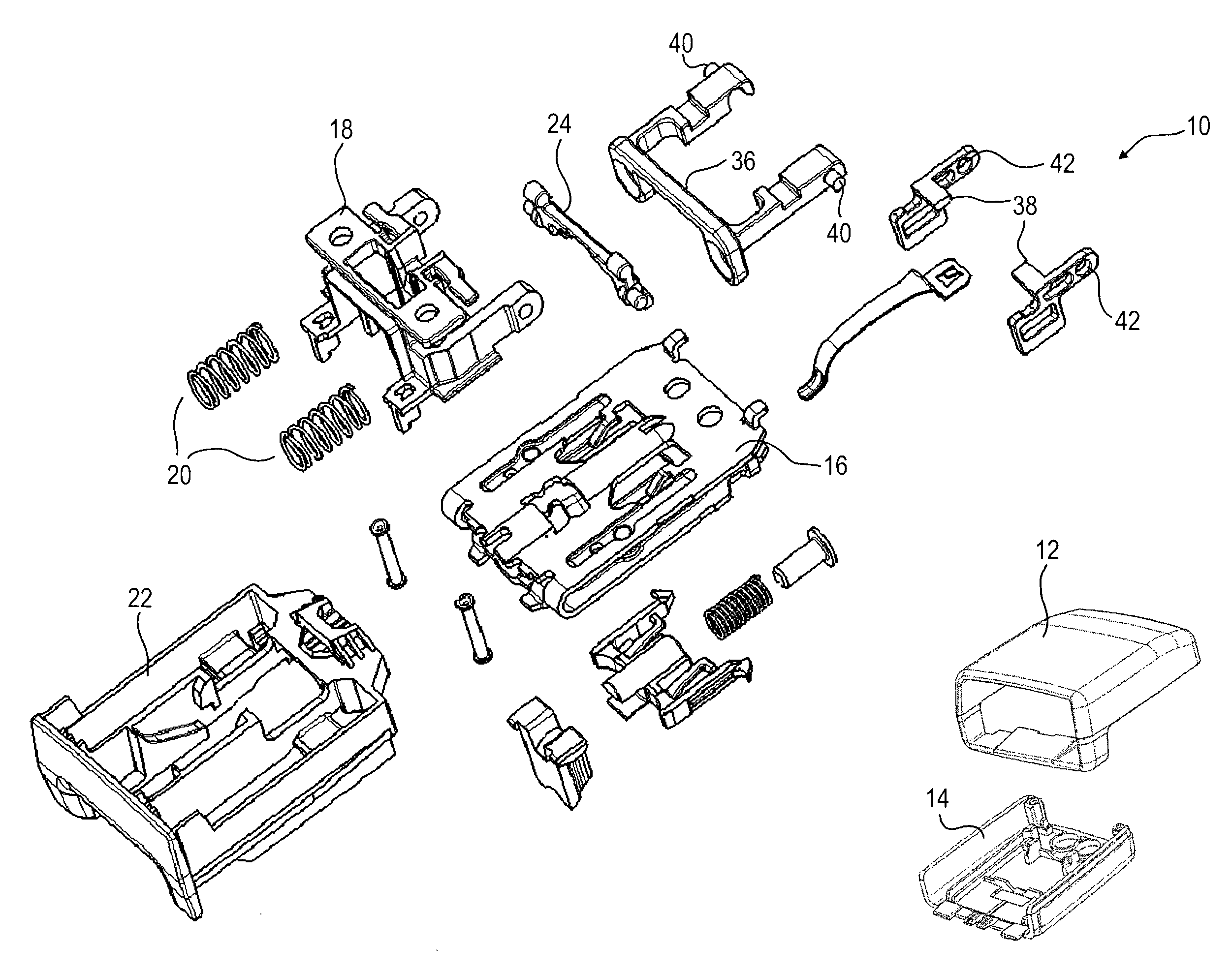
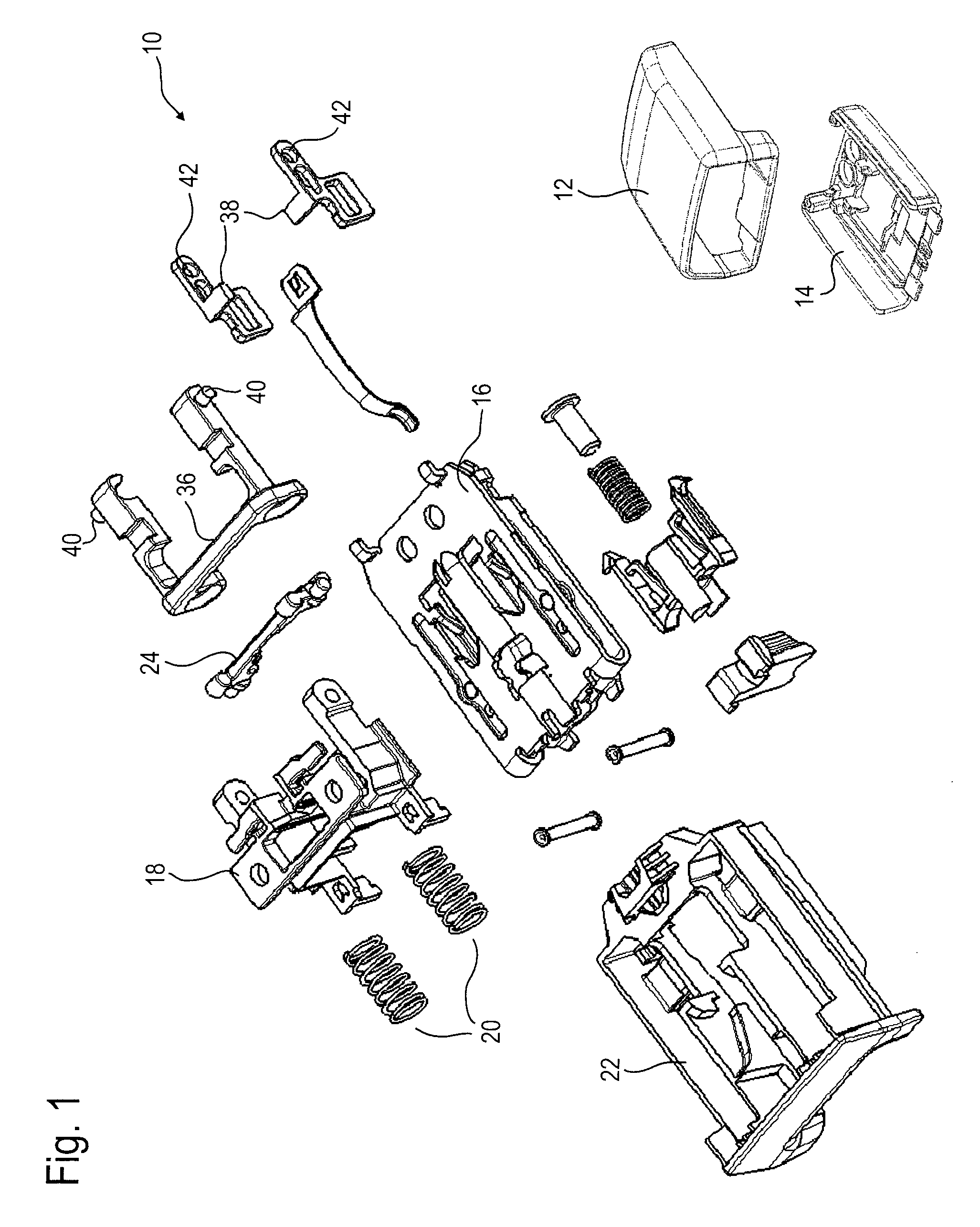
[0035]In FIGS. 1 to 11 a belt buckle 10 for a seat belt system is represented which is mounted tightly on the vehicle at a fitting, which is not shown, either directly or by a belt tensioner connected to the fitting. The housing shells 12, 14 are omitted in the FIGS. 2 to 11 so as to allow an unhindered view onto the inner components of the belt buckle 10. Hereinafter, among the components shown in FIG. 1 only the components relevant to the invention shall be discussed, as the basic structure and the basic functioning of a belt buckle 10 are provided as being known.

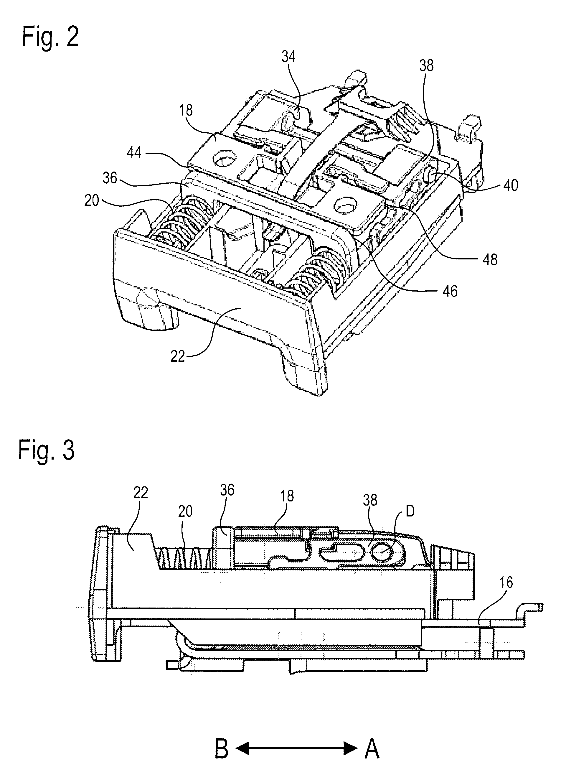
[0036]A detent cam guide 18 is fixedly mounted on a load-bearing buckle housing 16. Two compression springs 20 pretension a release button 22 configured in the form of a slide and being movable relative to the housing in the directions A and B in the direction (second direction) B opposite to the actuating direction (first direction) A.

[0037]A two-armed coupling lever 24 is rotatably supported on the detent cam guide 18 ...

second embodiment

[0047]In FIGS. 12 and 13 a belt buckle for a seat belt system is illustrated that exhibits a structure similar to the afore-described belt buckle 10 shown in FIGS. 1 to 11. Therefore, the same reference numerals have been used for corresponding components having the same function despite certain deviations in the concrete configuration, and in this respect the foregoing explanations concerning said components are referred to.

[0048]The substantial difference between the two embodiments consists in the fact that the belt buckle according to the second embodiment has a shorter overall length, because no pivot bodies 38 are provided. However, the retaining portion 48 is formed at the coupling lever 24 which is cranked. Accordingly, the holding portion 50 of the detent cam guide 18 fixed to the housing is arranged in a position opposite to the retaining portion 48. The interaction of the retaining portion 48 with the holding portion 50 shall be described in detail later.

[0049]FIG. 12 sh...


PUM


Abstract

A belt buckle (10) for a seat belt includes a buckle housing (16), a locking mechanism for locking a plug-in tongue inserted in the buckle housing (16), a release button (22) which is movable in a first direction relative to the buckle housing (16) for unlocking the plug-in tongue, and a safety mechanism for preventing automatic displacement of the release button (22) in the first direction. The safety mechanism includes a mass body (36) movable in the first direction relative to the buckle housing (16) and a movably supported coupling lever (24) including an axis of rotation which is stationary relative to the buckle housing (16). The coupling lever (24) is coupled to the mass body (36) and to the release button (22) so that, upon acceleration of the belt buckle (10) in a second direction opposed to the first direction, it transmits an inertia force acting on the mass body (36) in the first direction to the release button (22) in the opposite second direction.

Description

RELATED APPLICATIONS[0001]This application corresponds to PCT / EP2013 / 000340, filed Feb. 5, 2013, which claims the benefit of German Application Nos. 10 2012 002 207.7, filed Feb. 7, 2012 and 10 2012 018 070.5, filed Sep. 13, 2012, the subject matter, of which are incorporated herein by reference in their entirety.BACKGROUND OF THE INVENTION[0002]The invention relates to a belt buckle for a seat belt.[0003]Especially in the case of belt buckles coupled to a belt tensioner, there is the risk of the belt buckle opening automatically due to the high acceleration at the beginning or at the end of belt tensioning, if great inertia forces act on the components of the belt buckle. Release locks that are intended to prevent the belt buckle from opening inadvertently are known in different designs.[0004]EP 0 557 983 A1 illustrates a seat belt buckle comprising a latch lock in which in the case of great mass forces a latch pin serving as locking element is safely retained in a locking position...

Claims


Application Information

Patent Timeline
Patent Type & Authority Patents(United States)
IPC IPC(8): A44B11/25B60R99/00
CPCA44B11/2523A44B11/2515A44B11/2569B60R99/00Y10T24/45639Y10T24/45623Y10T24/45681
Inventor HAAS, PETER
Owner TRW AUTOMOTIVE GMBH
Why Eureka
Try Eureka