
Throwing sleeve with visual bio-feedback

a biofeedback and sleeve technology, applied in the field of athletic training methods and devices, can solve problems such as incorrect motion of users, and achieve the effects of reducing the need for expensive training spaces, improving the user's movement, and controlling the velocity of the ball

Active Publication Date: 2016-07-26
STOVER HERBERT A
View PDF20 Cites 2 Cited by
  • Summary
  • Abstract
  • Description
  • Claims
  • Application Information

AI Technical Summary

Benefits of technology

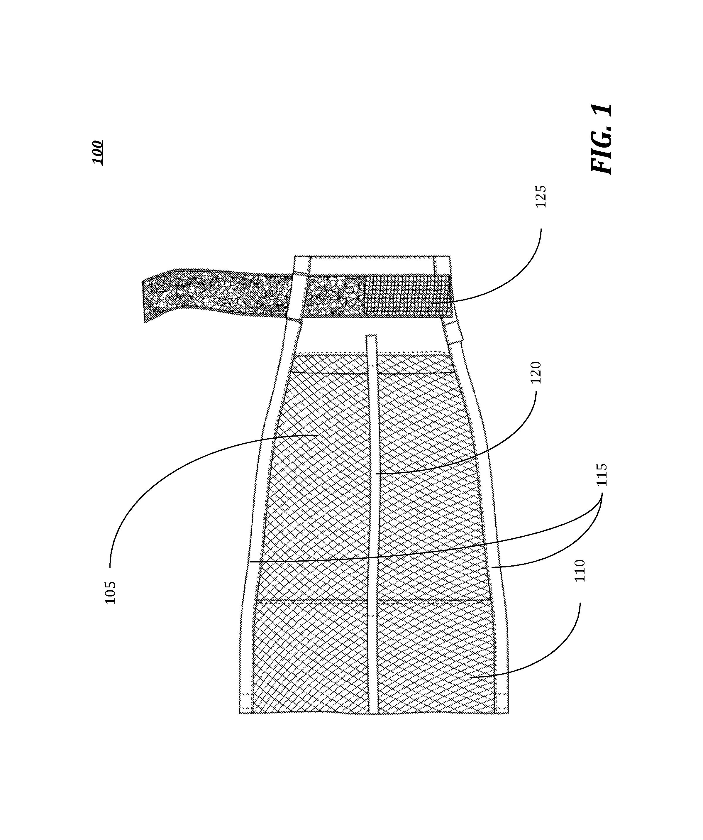
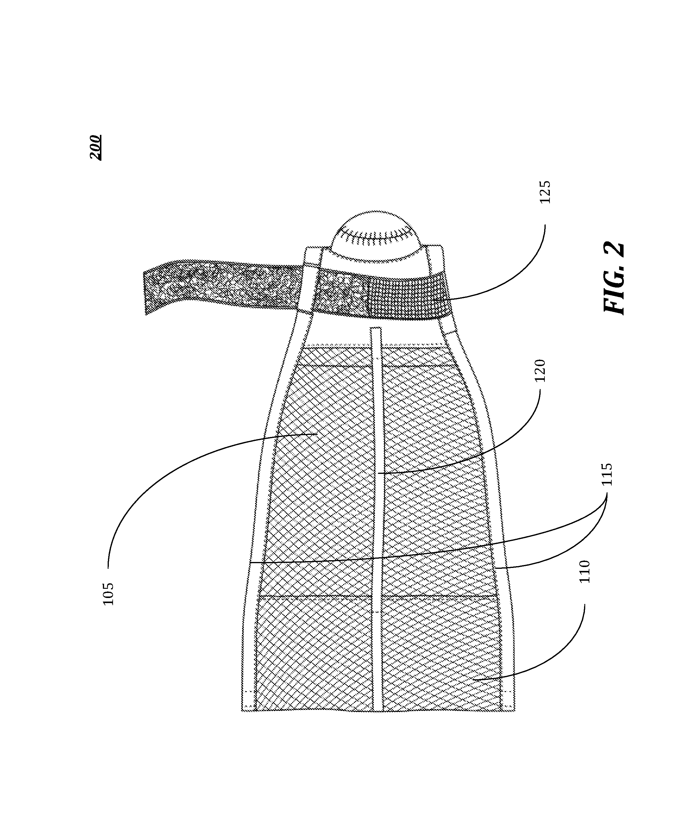
The patent is about a device called a "throwing sleeve with visual biofeedback" that can be used to teach proper arm position and wrist motion for throwing a ball. The device is designed to fit over a player's arm and contains markings that indicate the arm position throughout the throw. It can help improve the player's movement, control, and velocity of the ball, reducing the risk of injury. The device can also incorporate sensors to provide additional feedback on the throw. It may be used as a training tool for instructing on proper arm position and motion. The device can be a single-segment or multi-segment sleeve, and it may be made of mesh or reinforced material. Overall, the device helps to teach proper form and prevent arm and shoulder injuries during training.

Problems solved by technology

Moreover, the visual observation of the markings during the throw may further indicate where the user's motion is incorrect.

Method used


Image

  • Throwing sleeve with visual bio-feedback
  • Throwing sleeve with visual bio-feedback
  • Throwing sleeve with visual bio-feedback

Examples


embodiment 600

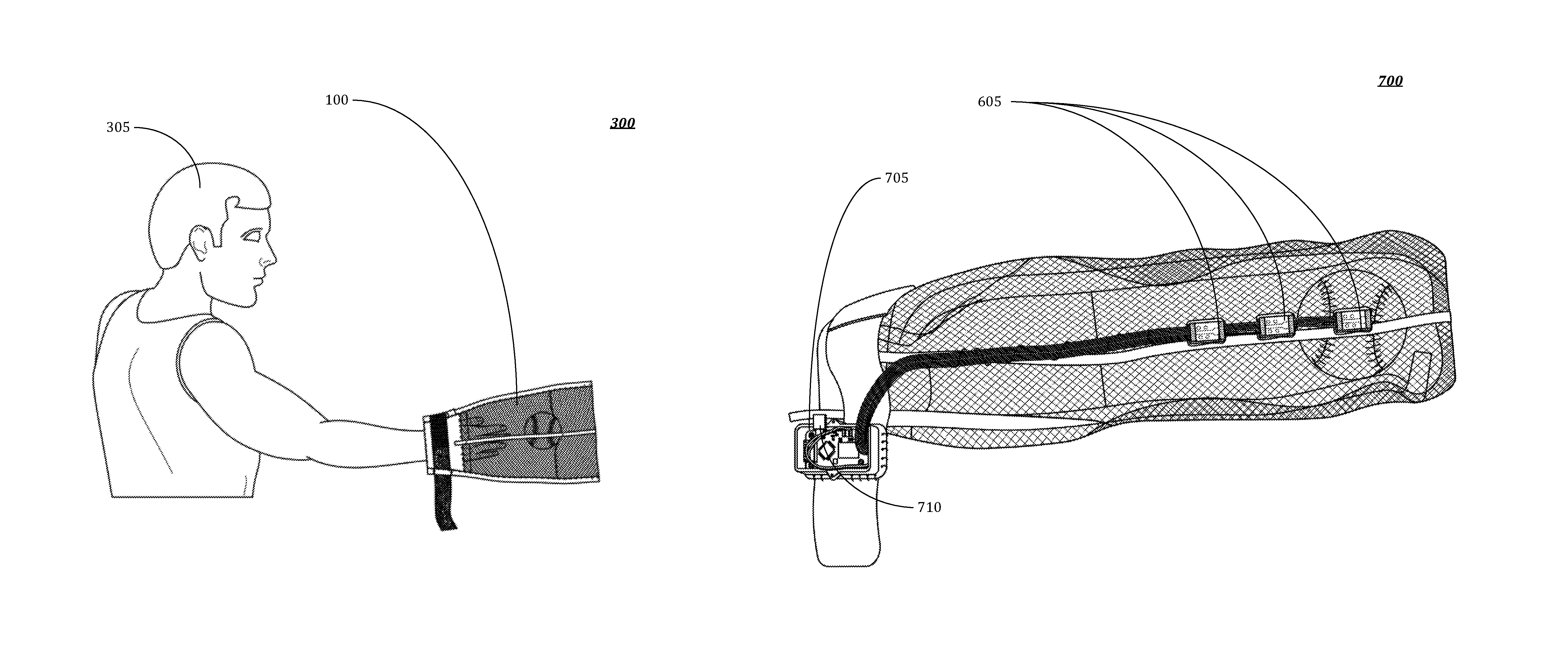
[0065]Embodiments of this device may further incorporate sensors to identify various aspects of, for example, a user's throw. FIG. 6 illustrates an embodiment 600 comprising sensors 605. These aspects may include, arm position, hand position, ball velocity, rotational speed, and direction. The sensors 605 may comprise, but not be limited to, devices capable of measuring acceleration, velocities, projectiles, axis of rotations, rotational speeds, direction of propagation (e.g., relative to, for example, a horizontal or vertical plane). Sensors may further be incorporated to provide measurements for gaming applications, such as, for example, virtual pitching in a baseball game.

embodiment 700

[0066]The sensors 605 used to detect these characteristics may be placed throughout the device (e.g. on the wristband and along the sleeve). FIG. 7 illustrates an embodiment 700 comprising sensors 605 and a component housing 705. The component housing 705 may comprises, for example, but not be limited to, a processing unit and a memory storage along with communication modules. One example on the components housed in housing 705 may include computing device 800.

[0067]In some embodiments, the sensors may be placed on, for examples, the user's fingers (e.g., embedded in the finger loop), hand, and arm or body part. Still consistent with embodiments of the present invention, the sensors may be in communication without sensors placed throughout the user's body.

[0068]The sensors may be configured with data transmission capability. In some embodiments, the sensors may comprise on-board communications components, while in other-embodiments, the communications module may be located in remote...


PUM


Abstract

A throwing sleeve with visual biofeedback may be provided. Embodiments of the present disclosure may be comprised of a sleeve. The sleeve may be comprised of a plurality of segments forming a single, internal passageway with at least one opening. A first opening may be configured to receive an object (e.g., baseball or softball) into the internal passageway of the sleeve. A second opening may be configured to receive a user's hand. Embodiments may further comprise a means for securing the user's hand within the internal passageway of the sleeve. Still further, embodiments may comprise at least one stripe running parallel to an edge of each of the plurality of segments.

Description

RELATED APPLICATION[0001]Under provisions of 35 U.S.C. §119(e), the Applicant claims the benefit of U.S. provisional application No. 62 / 006,645, filed 2 Jun. 2014, which is incorporated herein by reference.[0002]It is intended that each of the referenced applications may be applicable to the concepts and embodiments disclosed herein, even if such concepts and embodiments are disclosed in the referenced applications with different limitations and configurations and described using different examples and terminology.FIELD OF DISCLOSURE[0003]The present disclosure generally relates to athletic training methods and devices.BACKGROUND[0004]An athlete, such as, for example a baseball player, may frequently practice throwing a baseball to improve, for example, his pitch. After the ball is thrown, conventional training methods require the ball to be retrieved back to player by, for example, a catcher. A catcher, however, may not always be available, and it might not always be convenient to ...

Claims


Application Information

Patent Timeline
Patent Type & Authority Patents(United States)
IPC IPC(8): A63B69/00A63B24/00A63B71/06A63B23/12A63B69/36
CPCA63B69/0002A63B21/4021A63B23/12A63B24/0003A63B71/0619A63B69/3608A63B2069/0006A63B69/0059A63B2069/0008A63B2071/0625A63B2071/0647A63B2208/0204A63B2220/803A63B2225/50
Inventor STOVER, HERBERT A.
Owner STOVER HERBERT A
Learn More