Homogeneous fuel-air-mix method and apparatus for internal combustion engines

a fuel-air-mix and internal combustion engine technology, applied in the field of internal combustion engine fuel-air-mixing systems, can solve the problems of poor combustion of fuel, low engine performance efficiency, and high heat in the engin

Inactive Publication Date: 2016-07-05
BELTRAN CORONA JOSE MARIA
View PDF26 Cites 2 Cited by
  • Summary
  • Abstract
  • Description
  • Claims
  • Application Information

AI Technical Summary

Benefits of technology

[0005]The overall object of this invention is the increase in efficiency, reduction of overheating and pollution of exhaust in internal combustion engines. This is to be achieved through improvements of the air / fuel mixture ratio in combustion chambers. This is achieved through the elimination of the so-called “wet wall” effect following fuel injection into air in passages outside the combustion chambers. Other advantages, including simplification of computer programs in computers attached to engines, as well as some manufacturing efficiencies will accrue as a result.BRIEF SUMMARY OF THE INVENTION

Problems solved by technology

The main problem to a greater or lesser extent that previous or current technologies have in the field of air / fuel supply with carburetor as well as with fuel injection is poor combustion of fuel due to a bad air / fuel mixture.
This causes low efficiency of engine performance, high heat in the engine and high contamination emissions.
Numerous improvements have been devised to try to avoid the problem but, basically, these have only generated modest improvements.
Three-way catalytic converters are used to significantly reduce pollutant emissions to the atmosphere; however, gasoline consumption is not improved by this.
The use of catalytic converters causes a small increase in gasoline consumption by being an extra burden in the exhaust and a “resistance” to the flow of gases while also adding cost and vulnerability to the system.

Method used


Image

  • Homogeneous fuel-air-mix method and apparatus for internal combustion engines
  • Homogeneous fuel-air-mix method and apparatus for internal combustion engines
  • Homogeneous fuel-air-mix method and apparatus for internal combustion engines

Examples


Embodiment Construction

New Intake Manifold.

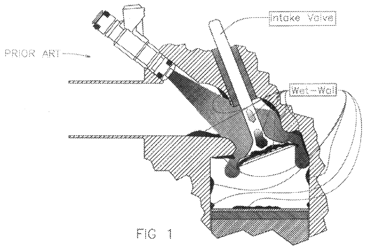
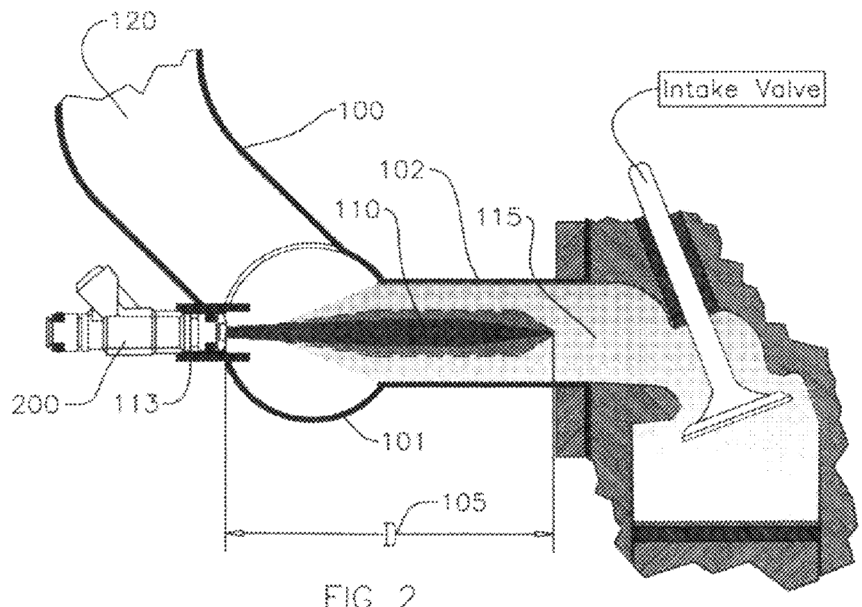
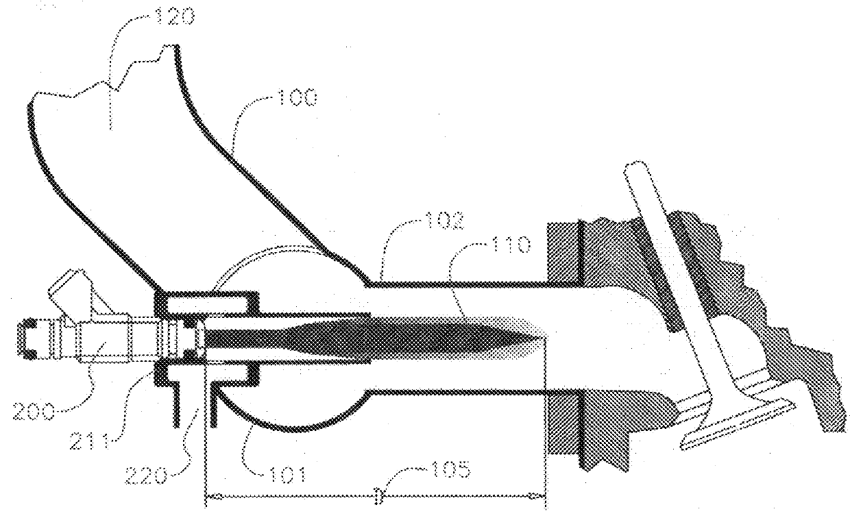
[0032]With reference to FIGS. 2, 3, 4. The injectors 200 are a type of current injector, attached to the new intake manifold section 101 via bracket 113 and through the new nozzles 210, 211, 212 or 213. Selecting said injector 200 (FIG. 2) by a jet of injected fuel that is most similar to that indicated in the figures with 110. It is preferable to use a nozzle whose jet of fuel to be injected does not touch the walls of the duct section 102 and the length or extent indicated by the distance D, 105 does not reach the intake valve as a result of injection pressure, but until the 110 jet as forming a “cloud” of air / fuel 115 is moved together with the air 120 by the sucking action of the pistons during the intake stroke when the intake valve is opening, thus avoiding the deleterious effect of wet wall. The inlet air 120 mixes inside the duct 102 with the fuel jet or cloud 110 forming a homogeneous mixture of fuel air 115 in FIG. 2 that is sucked into the combustion c...


PUM


Abstract

New strategies for control and feeding of air / fuel homogenous mix for internal combustion engines, mainly for fuel injection engines. This new strategies are to get an air / fuel mixture homogeneous and of adequate volume. Fuel in contact with air for a sufficient length of time required for better physical combination prior to the time of ignition at the spark plug and of a volume such that the combustion flame can reach the entire mixture admitted. Strategies to prevent the problem known as “wet wall”. This consisting of a new intake manifold, new fuel injectors, injector nozzles and new algorithms and strategies in the control software program of the ECU or MCU controlling the internal combustion engines.

Description

CROSS-REFERENCE TO RELATED PATENT APPLICATIONS[0001]This patent application is a non-provisional patent application of provisional patent application No. 61 / 540,859 filed on Sep. 29, 2011, the priority benefits of which are hereby claimed.INVENTION FIELD[0002]This invention relates to fuel injection systems for internal combustion engines used especially in vehicles. The invention consists of: a new feeding strategy of air / fuel mixture, new intake manifold, fuel injectors and control system programming including “software” of the computers in vehicles knows as “MCU” or “ECU”.BACKGROUND OF THE INVENTION[0003]The main problem to a greater or lesser extent that previous or current technologies have in the field of air / fuel supply with carburetor as well as with fuel injection is poor combustion of fuel due to a bad air / fuel mixture. This causes low efficiency of engine performance, high heat in the engine and high contamination emissions.[0004]Numerous improvements have been devised to...

Claims


Application Information

Patent Timeline
Patent Type & Authority Patents(United States)
IPC IPC(8): F02M61/14B05B1/34F02M69/04F02M29/04F02M23/00F02M69/08F02M35/10F02D41/00F02D41/12F02D41/32F02D35/02
CPCF02M69/044F02M23/003F02M29/04F02M35/10072F02M35/10216F02M69/047F02M69/08F02D35/027F02D41/0087F02D41/123F02D41/32F02M23/006Y02T10/146Y02T10/148Y02T10/12
Inventor BELTRAN CORONA, JOSE MARIA
Owner BELTRAN CORONA JOSE MARIA
Why Eureka
Try Eureka