
Method of simulating engine operation

a technology of engine operation and simulation method, applied in the field of simulating engine operation, can solve the problems of only being able to represent mean value modelling, not being able to obtain simulation results on a real-time basis, and inaccurate results, so as to increase the efficiency of engine simulation, accurate and efficient simulating engine operation, and accurate simulation results

Active Publication Date: 2016-05-31
RICARDO SIMULATION LTD
View PDF8 Cites 3 Cited by
  • Summary
  • Abstract
  • Description
  • Claims
  • Application Information

AI Technical Summary

Benefits of technology

The invention is a simplified engine model that can accurately and efficiently simulate engine operation. It contains sufficient information to produce accurate simulation results while still being suitable for real-time implementation. This model can be tailored by the user and can be used in development and testing of engine control strategies without relying on calibration data. The model employs simplified mathematical functions and harnesses the operational characteristics of the modeling hardware to increase the efficiency of engine simulation. This model can be used in any of software, hardware, or real engine environment. These technical effects provide a practical method and tool for accurately and efficiently simulating engine operation.

Problems solved by technology

However, the results obtained are inaccurate due to the degree of approximation used.
However, due to the complexity of the computations involved, it is not possible to obtain simulation results on a real-time basis using known crank-resolved modelling techniques.
However, mean value modelling is only capable of representing the output effects of engine behaviour.
Nor do they attempt to capture wave-action effects caused by pressure propagating along pipes in an engine.
The results output are therefore based on approximations for most of the vehicle, which compromises the accuracy of the results obtained from the simulation.
A problem which remains with existing modelling techniques is the inability to model in-cycle engine events to produce accurate simulation results on a real-time basis.
Instead, current methods focus on increasing the complexity of crank resolved models, making them less suitable for producing real-time simulation results, and then relying on approximated control-based models in real-time simulations.

Method used


Image

  • Method of simulating engine operation
  • Method of simulating engine operation
  • Method of simulating engine operation

Examples


Embodiment Construction

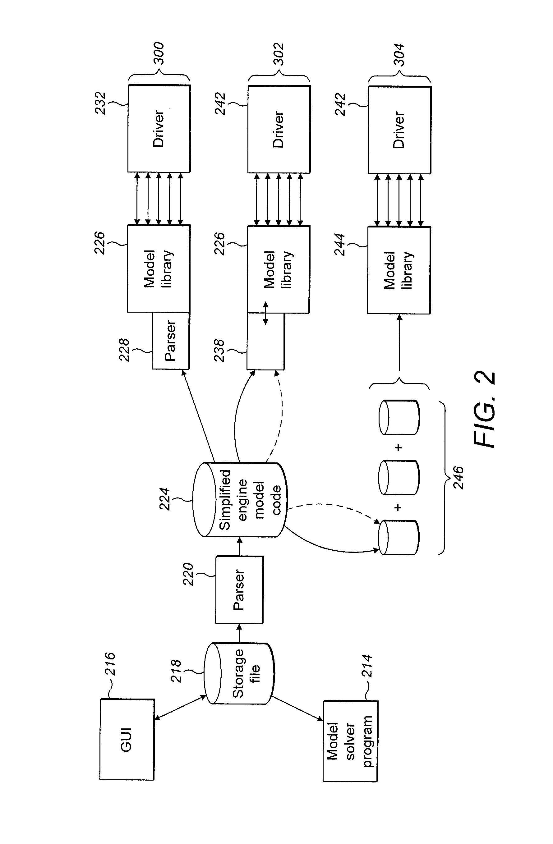
[0022]In overview, the invention relates to a method of creating a simplified engine model for simulating engine operation. A modelling tool is employed which uses information from a complete engine model to create the simplified engine model. This simplified engine model can then be used to simulate engine operation and produce accurate simulation results in real time. The simplified engine model can run in several different simulation or other operational environments, including software-in-the-loop, hardware-in-the-loop and within an engine control unit.

[0023]Referring to FIG. 1, the control interfaces for models or model components according to the present invention can be seen in more detail. The interfaces are between an engine model 110 comprising a description of basic engine model components or building blocks along with their connectivity and parameters, an existing complete vehicle model 112 and a number of different engine control development and test systems 116, 118, 1...


PUM


Abstract

A method of creating a simplified computer implementable engine model includes obtaining a complete computer implementable engine model and selecting, from the complete engine model, elements defining the simplified engine model. The method further includes obtaining from a library of rules at least one computer implementable model creation rule corresponding to the selected elements and using that at least one rule to create the simplified computer implementable engine model.

Description

BACKGROUND[0001]1. Field of the Disclosure[0002]This invention relates to a method of simulating engine operation, and particularly to creating a simplified engine model.[0003]2. Background Art[0004]A range of modelling approaches is known for simulating engine operation. These are used, for example, in the development and testing of control strategies for engines. In many cases, due to their simplicity, modelling approaches enable simulation results to be obtained quickly. However, the results obtained are inaccurate due to the degree of approximation used.[0005]A more complex known modelling technique is crank-resolved modelling. In crank resolved models, the cylinders of an engine are divided into sections. The propagation effects along the cylinders are then analysed. In crank resolved simulations, full partial differential equations are solved in order to capture wave-action effects in an engine. This approach to modelling is accurate as it looks at engine characteristics, and ...

Claims


Application Information

Patent Timeline
IPC IPC(8): G06G7/48G05B17/02
CPCG05B17/02
Inventor TRUSCOTT, ANTHONY J.NORRIS, ROBERT DAVIDAMPHLETT, STEVEN ANDREWMILLER, PETER JOHN
Owner RICARDO SIMULATION LTD
Learn More