Spinning machine having a compaction device

a technology of compaction device and spinning machine, which is applied in the direction of continuous wounding machine, drafting machine, textiles and paper, etc., can solve the problems of complex installation of compressive force elements, high time expenditure for handling periodic maintenance tasks, and large amount of time that must be calculated for returning the spinning machine to the wing frame without compaction, etc., to achieve quick and easy assembly and/or disassembly

Active Publication Date: 2016-05-31
MASCHINENFABRIK RIETER AG
View PDF16 Cites 2 Cited by
  • Summary
  • Abstract
  • Description
  • Claims
  • Application Information

AI Technical Summary

Benefits of technology

[0008]Using the presently proposed device, upon actuation of only a single pressure lever, it is possible to move both systems (the pressure rollers of the drafting arrangement unit and the compaction unit) into their operating position and fix them in place in that position. The result is easy and quick operability. Due to the single or multiple spring elements, the compaction unit is held in the operating position into which it was pivoted and in which it constitutes, together with the lower rollers of the delivery roller pair, a drive connection (for example, by means of friction). Moreover, via the spring element that is mounted to the pressure lever, the drafting arrangement unit is directly coupled to the compaction unit, when said drafting arrangement unit is in the operating position, wherein the result in a closed unit that is also less susceptible to vibrations.
[0013]Instead of a spring-loaded retainer, it is also possible to envision the spring element as a leaf spring that is directly fastened to the pressure lever. The result is a simplified structural assembly that has the same effect.
[0014]Furthermore, it is proposed to provide the support with a suction channel having one end that opens in the area of the pivot point of the support and one end that opens in the area of a suction insert that extends into the compaction element. The result is a compact unit, which also has the suction channel integrated therein and which can be locked, via the coupling point, as a total unit with the pressure lever; meaning, the compaction unit complete with integrated suction channel constitutes a compact and closed structural unit that can be quickly and easily assembled and / or disassembled, as required.
[0015]Further, it is proposed that the support be provided with a U-shaped end piece by which, when in the mounted position, the same partially grasps around a circular channel at the location of a coupling point, and the channel is fastened to the machine frame and connected to a negative pressure source. This ensures a problem-free and easy hook-up of the compaction unit to the machine frame in a first non-operating position, prior to the unit being transferred and fixed in the operating position by means of the pressure lever and the lever that is fastened thereto. However, other solutions for fastening the compaction unit and / or the support thereof via a pivot axis to the machine frame are conceivable.
[0017]It is further proposed that the pinch roller (also referred to as “twist-stop”) is disposed, with the ability to rotate freely, on a compressive arm that is pivotably mounted on the support. For a compact and closed configuration, it is advantageous therein to provide a spring element between the pivot axis of the compressive arm and the axis of rotation of the roller. On grounds of fibre fly in a spinning mill, a closed design of moving elements (for example, spring elements) is advantageous to avoid soiling of these parts.

Problems solved by technology

However, the amount of time that must be calculated for returning the spinning machine to a drafting arrangement unit wing frame without compacting is considerable.
Handling periodic maintenance tasks also involves a substantial time expenditure, if the compaction device must be disassembled each time.
Special installation of such compressive-force elements is complex; in addition, the compressive-force elements must be precisely adjusted to accommodate the compaction roller to which the load must be applied.
Moreover, this solution does not allow for a direct, matched positioning of the pivotable pressure lever of the nip rollers of the drafting arrangement unit in conjunction with the pivotable structural compaction component, which can be disadvantageous, for example, if the individual rollers are not exactly aligned with each other.

Method used


Image

  • Spinning machine having a compaction device
  • Spinning machine having a compaction device
  • Spinning machine having a compaction device

Examples


Embodiment Construction

[0034]Reference will now be made to embodiments of the invention, one or more examples of which are shown in the drawings. Each embodiment is provided by way of explanation of the invention, and not as a limitation of the invention. For example features illustrated or described as part of one embodiment can be combined with another embodiment to yield still another embodiment. It is intended that the present invention include these and other modifications and variations to the embodiments described herein.

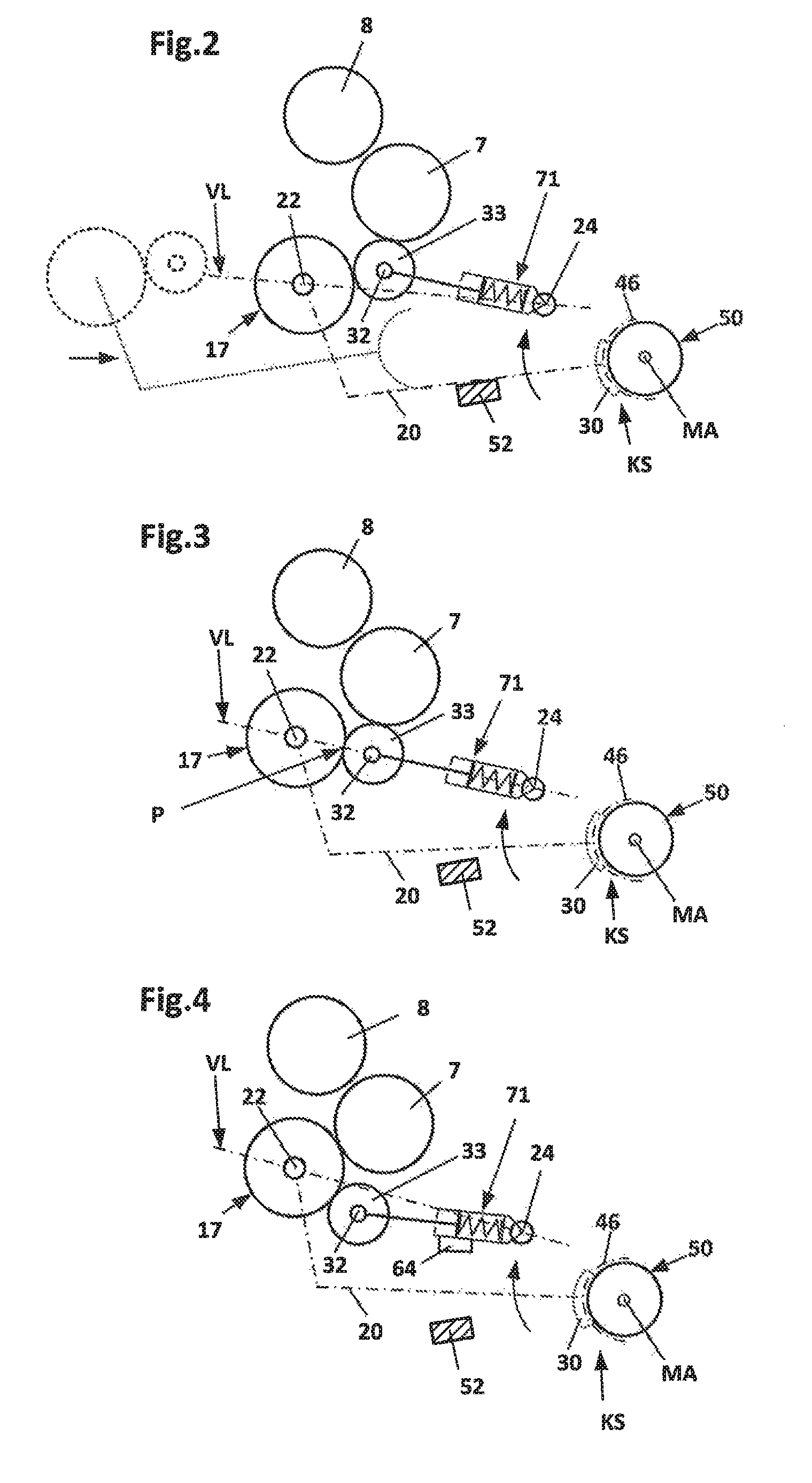
[0035]FIG. 1 shows a schematic side view of a spinning station 1 of a spinning machine (ring spinning machine) with a drafting arrangement unit 2 that is provided with an entry roller pair 3, 4, a center roller pair 5, 6 and a delivery roller pair 7, 8. One small apron 12, 13 is guided, respectively, around the center rollers 5, 6 that are held in place by a cage, presently not shown in further detail. The upper rollers 4, 6, 8 of the mentioned roller pairs are designed as pressure...


PUM

PropertyMeasurementUnit
compressive forceaaaaaaaaaa
pressureaaaaaaaaaa
axis of rotationaaaaaaaaaa

Abstract

A device for compacting a fiber composite on a spinning machine includes consecutive drafting arrangement roller pairs. A compaction unit is pivotably mounted on the machine frame downstream of the delivery roller pairs with a pivot axis parallel to the rotational axes of the delivery roller pair, and includes a support with a suction drum rotatably supported on the support. At the end of a suction zone of the drum, a nip roller is fastened to the support to form a nip line. The support is spring-loaded to form a drive connection between the lower roller of the delivery roller pair and the suction drum, wherein the suction drum is moved against the lower roller. Guide means fix the compaction unit in position as mounted on the machine frame, and the spring element is mounted on the free end of the pressure lever.

Description

FIELD OF THE INVENTION[0001]The invention relates to a device compacting a fiber composite on a spinning machine with a drafting arrangement unit including consecutively arranged drafting arrangement roller pairs having pressure rollers that are held in place on a pressure lever, which is pivotably supported on the machine frame, and with a pivotably mounted compaction unit downstream of the delivery roller pair of the drafting arrangement unit on the machine frame.[0002]A multitude of configurations is known in the art from practical applications, wherein a compacting means is disposed downstream of a drafting arrangement unit for the purpose of compacting the fiber material (fiber strand) that is discharged by the drafting arrangement. Downstream of such a compacting means, and after traversing a nip, the compacted fiber material is fed to a device that generates a twist. On a ring spinning machine, a twist-generating means of this kind includes, for example, a traveller that rota...

Claims


Application Information

Patent Timeline
Patent Type & Authority Patents(United States)
IPC IPC(8): D01H5/86D01H5/72D01H1/02D01H5/74
CPCD01H5/86D01H1/025D01H5/72D01H5/74
Inventor SCHNEIDER, GABRIELMALINA, LUDEKNAGELI, ROBERT
Owner MASCHINENFABRIK RIETER AG
Why Eureka
Try Eureka