
Utility vehicle

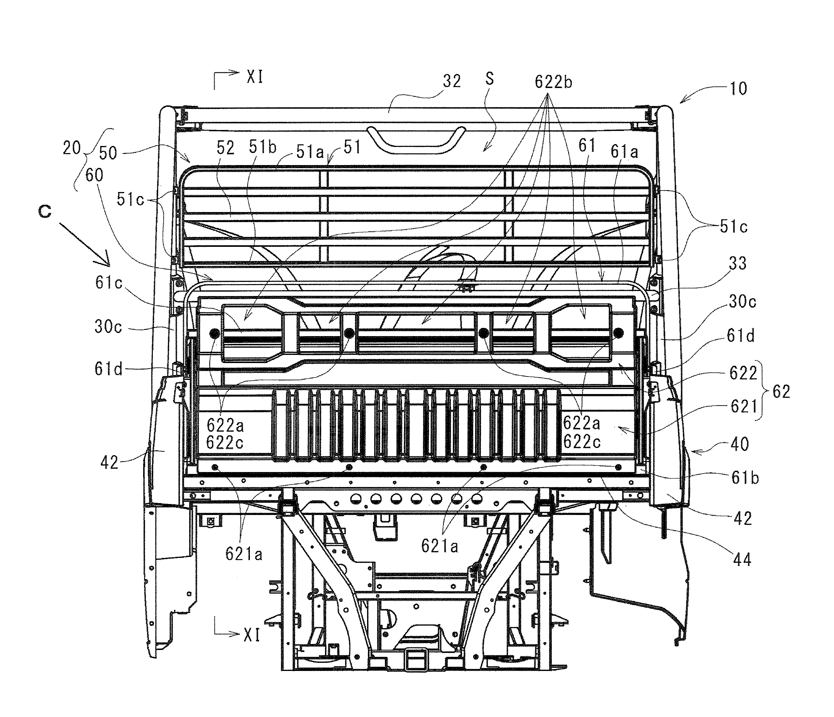
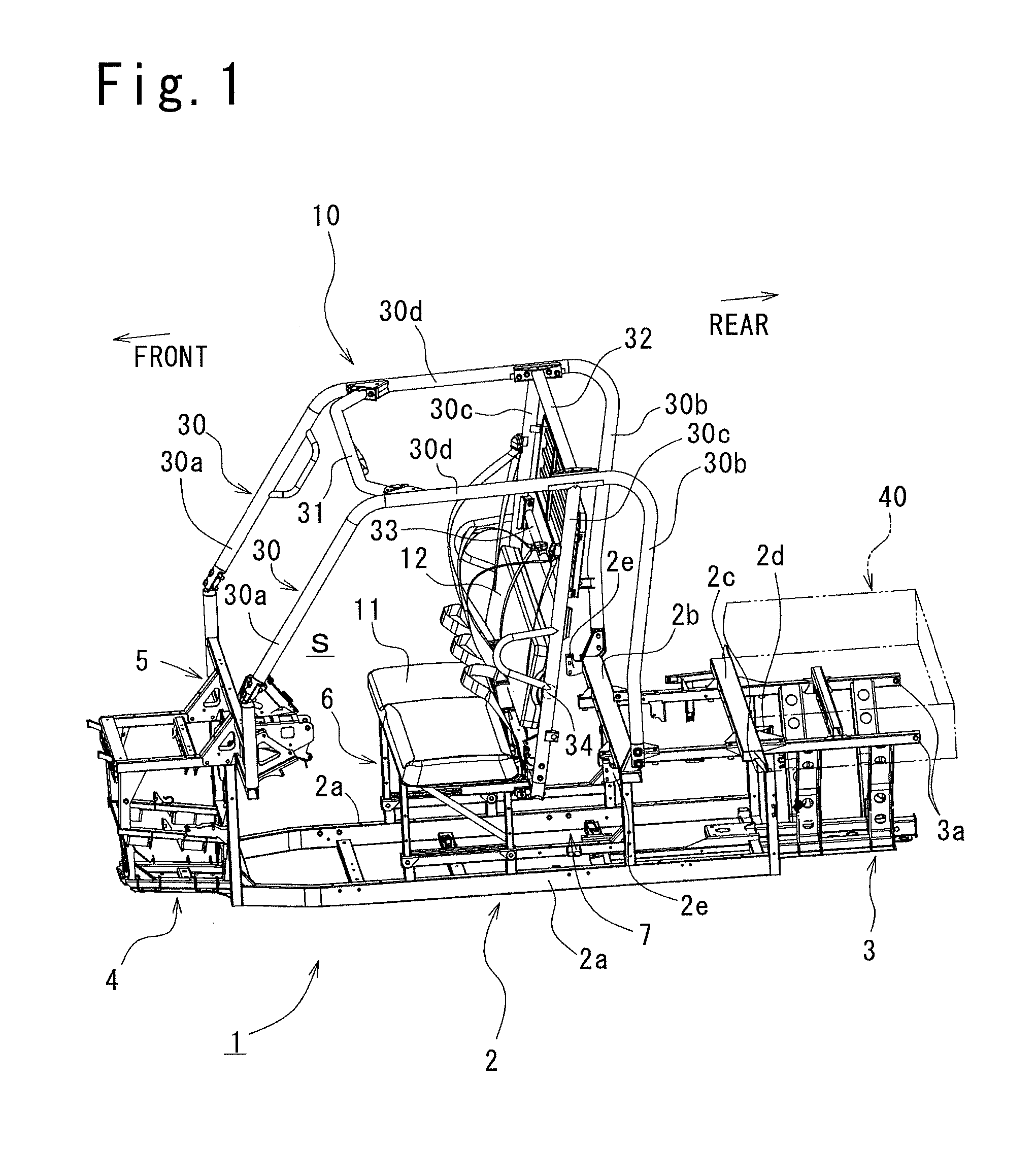
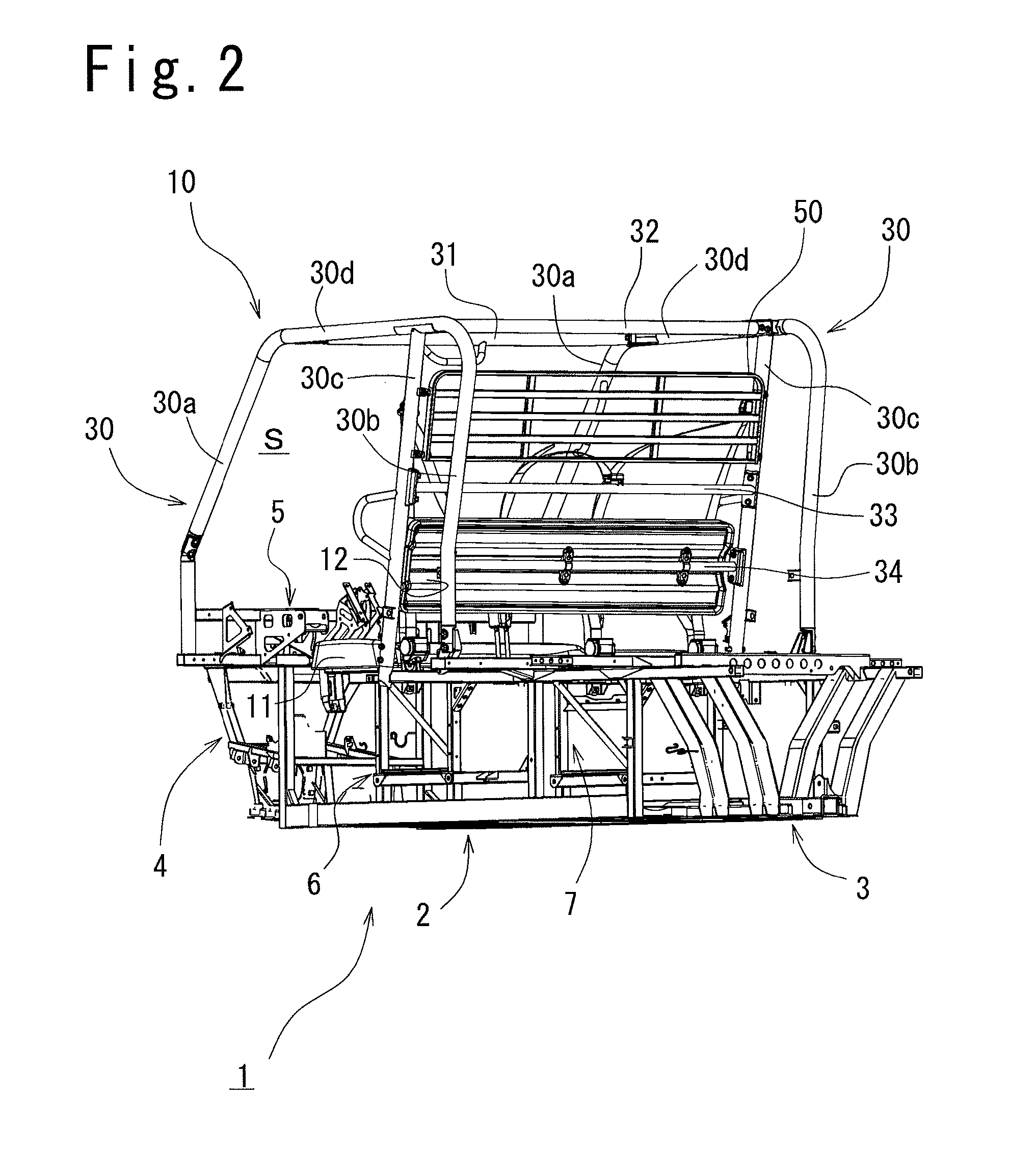
a technology for utility vehicles and trailers, applied in the direction of vehicular safety arrangements, transportation items, pedestrian/occupant safety arrangements, etc., can solve the problems of increasing the time and labor required for dump work in which the cargo bed is raised, the rotation locus of the cargo bed may interfere with the roof portion, and the rotation locus may increase. , to achieve the effect of maintaining the rigidity of the upper screen

Active Publication Date: 2016-05-31
KAWASAKI MOTORS LTD
View PDF7 Cites 7 Cited by
  • Summary
  • Abstract
  • Description
  • Claims
  • Application Information

AI Technical Summary

Benefits of technology

This configuration enhances design freedom, marketability, and workability by minimizing weight and interference issues, ensuring rearward visibility and efficient dump operations without compromising rigidity or increasing costs.

Problems solved by technology

In particular, in the case that the cargo bed is a dump type, time and labor required for dump work in which the cargo bed is raised increase because of the increase in the weight of the cargo bed.
In addition, the rotation locus of the cargo bed increases during the dump work, and the rotation locus may interfere with the roof portion of the chassis of the vehicle, surrounding objects located around the upper part of the utility vehicle, etc. in some cases.
In other words, in the case that a screen is added to the cargo bed, the screen is required to be designed in consideration of the interference of the rotation locus of the cargo bed with the roof portion of the chassis, surrounding objects located around the upper part of the utility vehicle, etc. whereby the degree of freedom of designing the screen is limited.

Method used


Image

  • Utility vehicle
  • Utility vehicle
  • Utility vehicle

Examples


embodiment 1

[0088]Moreover, it is also possible to adopt an upper screen 100 according to another embodiment 1 shown in FIG. 13. The upper screen 100 is equipped with an upper frame portion 110 and an upper screen body portion 120. Punched-out openings 121 such as those of lath metal and having a size large enough to allow the passengers of the vehicle to confirm the rearward view of the vehicle are formed in the inner area of the upper screen body portion 120 excluding its peripheral portion. Hence, the cost of the screen can be made lower than that in the case that lath metal, punching metal or the like is adopted, while the rearward visibility through the upper screen 100 is ensured.

[0089]The reason for this cost reduction is described below. Since the peripheral portion of lath metal or the like is discontinuous, it is not easy to join the entire circumference of the peripheral portion to frame members. The peripheral portion is held between a pair of frame members around the entire circumf...

embodiment 2

[0090]Still further, an upper screen 200 according to another embodiment 2 shown in FIG. 14 can also be adopted. The upper screen 200 is equipped with an upper frame portion 210 and an upper screen body portion 220. The upper screen body portion 220 is made of a transparent member so that the passengers of the vehicle can confirm the rearward view of the vehicle; for example, the upper screen body portion 220 can be made of transparent resin, such as polycarbonate resin.


PUM

PropertyMeasurementUnit
widthaaaaaaaaaa
lattice shapeaaaaaaaaaa
transparentaaaaaaaaaa

Abstract

A utility vehicle is equipped with a R.O.P.S. enclosing a passenger space, a cargo bed disposed behind the passenger space, and a screen disposed between the passenger space and the cargo bed. The screen is divided into an upper screen and a lower screen.

Description

BACKGROUND OF THE INVENTION[0001]1. Field of the Invention[0002]The present invention relates to a utility vehicle, and more particularly, to a utility vehicle in which a screen is disposed between a cargo bed and a passenger space (riding space).[0003]2. Description of the Related Art[0004]In a utility vehicle, a screen is disposed between a passenger space and a cargo bed. This kind of screen is made of a member having openings, such as lath metal, so that the passengers of the vehicle can confirm the rearward view of the vehicle through the screen.[0005]For example, the specification of U.S. Pat. No. 6,905,159 has disclosed a utility vehicle in which a screen is disposed in the front portion of a cargo bed.[0006]In the case that the screen is disposed in the cargo bed, the weight of the cargo bed increases. In particular, in the case that the cargo bed is a dump type, time and labor required for dump work in which the cargo bed is raised increase because of the increase in the we...

Claims


Application Information

Patent Timeline
Patent Type & Authority Patents(United States)
IPC IPC(8): B60R21/13B62D33/06B60P1/28B29C35/08B29D11/00B29C37/00
CPCB29C35/08B29C37/0032B29D11/00038B29D11/00903B29C2035/0827B29C2037/0046B60R21/026B60R21/13B60P1/283B62D33/0625B62D33/02
Inventor TAKAHASHI, KEIJITSUMIYAMA, YOSHINORI
Owner KAWASAKI MOTORS LTD
Learn More