
Magnetically mounted privacy screen

Active Publication Date: 2016-05-24
DAVILA JR GILBERTO
View PDF25 Cites 17 Cited by
  • Summary
  • Abstract
  • Description
  • Claims
  • Application Information

AI Technical Summary

Benefits of technology

The present invention aims to provide a privacy screen that can effectively block windows and other wall openings in institutions like correctional and medical facilities. The screen can be quickly and securely attached to the metal frame of a window or opening, completely blocking viewing. Additionally, the privacy screen offers more complete coverage of the window or opening, resulting in improved privacy and blocking of viewing.

Problems solved by technology

Currently, there are no known removable window screens that provide such a one way observational capability.
This normally provides incomplete or otherwise unsatisfactory privacy.
The conventional folding screen is typically not configured to match the size and shape of a particular window or wall opening.
In addition, the foldable screen usually includes gaps or openings between the adjoining screen components, which provides additional unwanted exposure through the covered window.
Typically, these screens are bulky and awkward to transport around the facility.
They also require a considerable amount of space, both when being used and while in storage.
When the screen is not in use, it takes up valuable and limited storage space.
These types of screens also require tedious and time consuming assembly and frequently have to be repaired or replaced.
Folding / rolling screens are obviously not feasible for use in blocking the windows of automotive vehicles or for other applications such as darkrooms.
Although previous window blankets and bug screens have employed magnets for mounting across a window, such known devices have been unsuitable for use as privacy panels both in correctional facilities and at outdoor accident and crime scenes.
The conventional products can be awkward and time consuming to install, manipulate and remove.
In addition, these screens lack versatility and cannot be supported either magnetically or by non-magnetic means such as mounting poles when nearby magnetically attractive metallic structure is unavailable.

Method used


Image

  • Magnetically mounted privacy screen
  • Magnetically mounted privacy screen
  • Magnetically mounted privacy screen

Examples


Embodiment Construction

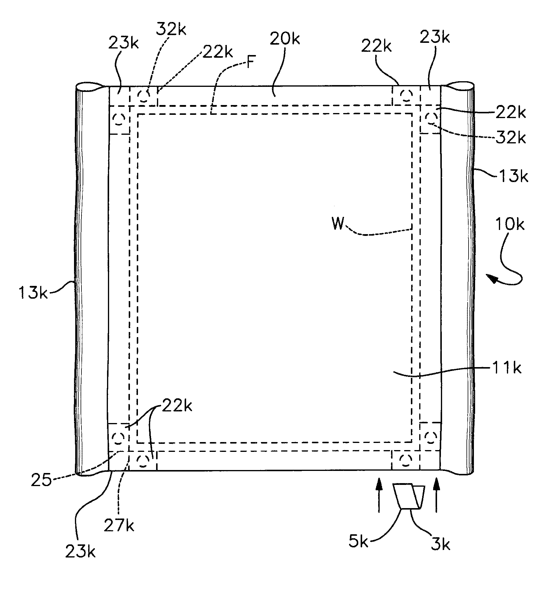
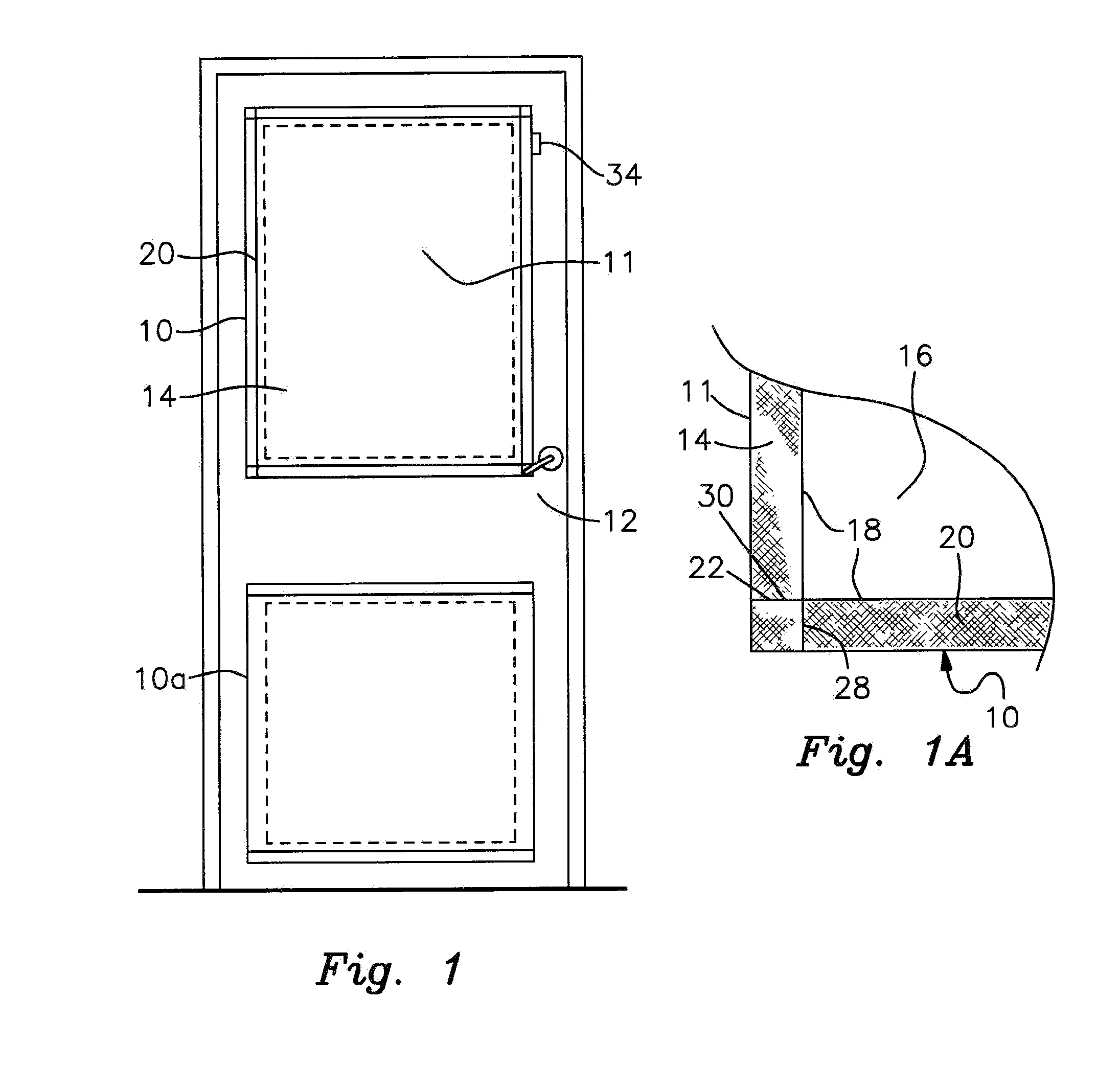
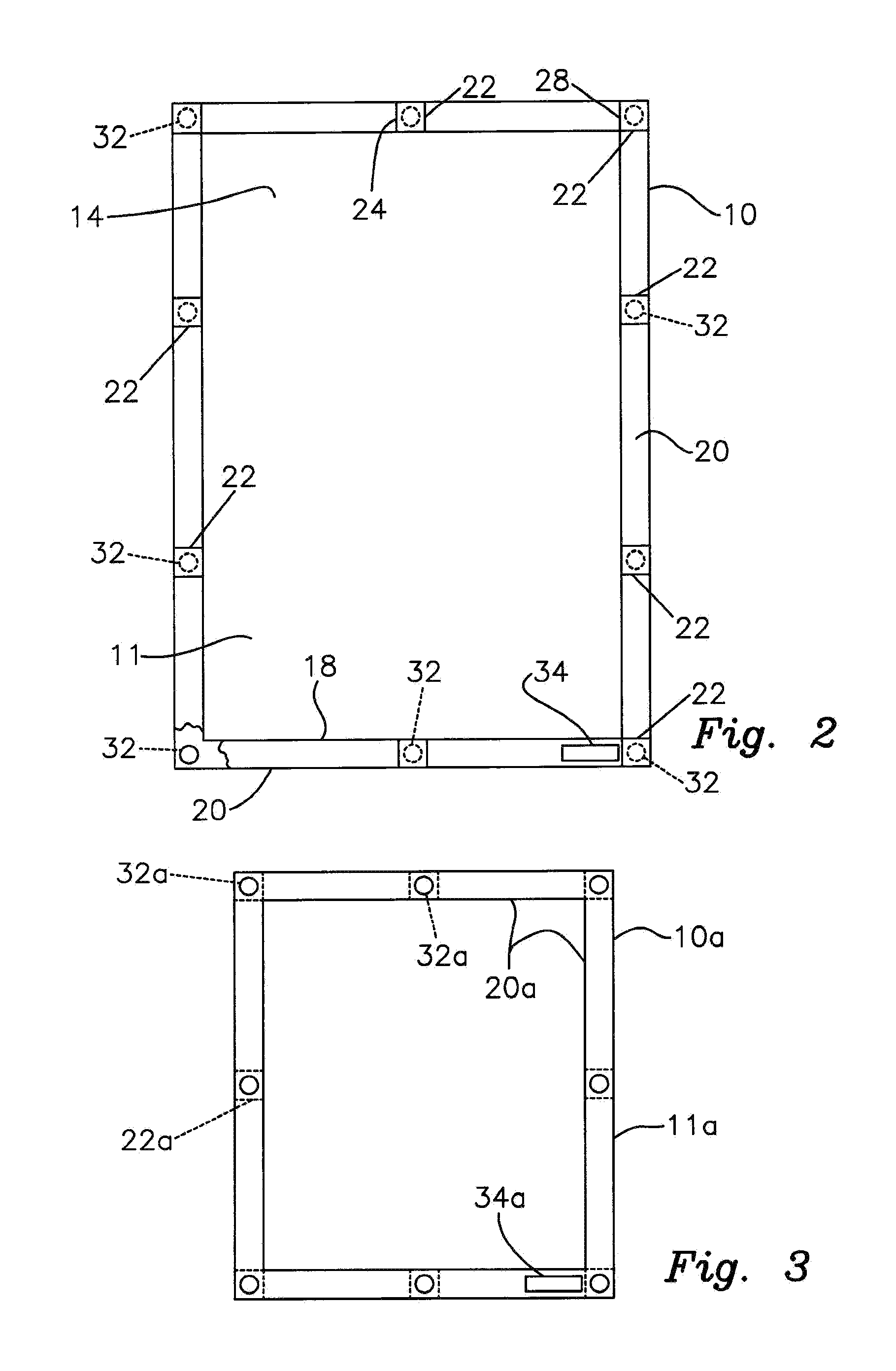
[0038]There is shown in FIG. 1 a pair of magnetically mounted privacy screens or blinds 10, 10a for covering the upper and lower windows respectively of a standard steel door 12. This is a security door as is commonly found in jails, prisons and other types of correctional facilities. It should be understood that the privacy screen of this invention may be used to cover windows and other types of openings in a wide variety of doors, walls and other building structures. Although use of the magnetically mounted screen disclosed herein is especially effective and advantageous in correctional facilities, hospitals and other institutional settings, wherein the window or other wall opening to be covered is enclosed by a metallic frame, it should be understood that the screen may also be beneficially utilized in various other applications, such as for covering vehicle windows, darkroom windows, etc. The particular setting, venue or application in which the screen is employed does not const...


PUM


Abstract

A privacy screen includes a flexible panel having a hem formed peripherally about the panel. The hem includes a plurality of pockets. Each pocket accommodates a respective magnet. The magnets releasably adhere to a metallic door or frame surrounding a window or wall opening to be covered. This holds the panel over the window or wall opening to prevent viewing therethrough.

Description

RELATED APPLICATION[0001]This application is a continuation in part of U.S. patent application Ser. No. 13 / 200,637, filed Sep. 27, 2011, which application claims the benefit of U.S. Provisional Patent Application Ser. No. 61 / 404,065 filed Sep. 27, 2010.FIELD OF THE INVENTION[0002]This invention relates to a portable privacy screen or blind for covering an interior window or other wall opening or, alternatively, an outdoor accident or crime scene. More particularly, the screen may be magnetically mounted to a metallic frame surrounding the window or wall opening. The magnetically mounted privacy screen is especially effective for use in correctional facilities, hospitals and other institutional settings. The versatile screening may also be mounted on vertical poles received by sleeves formed in the screen.BACKGROUND OF THE INVENTION[0003]Many types of facilities require the occasional use of privacy blinds and screens to cover windows and other wall openings in rooms or other interio...

Claims


Application Information

Patent Timeline
IPC IPC(8): A47G5/00A47H99/00A47H1/00E06B9/24A47H23/02
CPCA47H1/00E06B9/24A47H99/00A47H2023/025A47H2201/01E01F7/00E06B7/28
Inventor DAVILA, JR., GILBERTO
Owner DAVILA JR GILBERTO
Learn More