Method for manufacturing binocular loupe

a binocular loupe and manufacturing method technology, applied in the field of binocular loupes, can solve the problems of insufficient accuracy from a viewpoint of accuracy, the error of inter-pupil distance, and the conventional binocular loupe for operation in a downward postur

Active Publication Date: 2016-05-10
ACP JAPAN +1
View PDF4 Cites 8 Cited by
  • Summary
  • Abstract
  • Description
  • Claims
  • Application Information

AI Technical Summary

Benefits of technology

[0022]Further, the loupe units may have fixed magnification power to provide enlarged view of the operational manipulating position or a zooming function with variable magnification power within a predetermined range.
[0030]Further, the inward wearing angles p, q in the step (f) may be set to be smaller with increase of a corneal apex distance between a corneal of the operator and a back surface of the carrier lens.
[0035]With the method for manufacturing a binocular loupe according to the present invention, an operator wearing a frame takes a working posture, strobe light is radiated toward the face section of the operator from an operational manipulating position at which the operator operates at hand, and reflected light is photographed with an imaging device so as to detect pupil positions from the photographed image. Accordingly, the pupil positions can be accurately specified in accordance with the working posture, so that a binocular loupe can be manufactured appropriately for each operator.

Problems solved by technology

Accordingly, a measurement result of the PD meter causes errors against an inter-pupil distance in a surgery posture.
Therefore, a conventional binocular loupe for operation in a downward posture has been insufficient from a viewpoint of accuracy.

Method used


Image

  • Method for manufacturing binocular loupe
  • Method for manufacturing binocular loupe
  • Method for manufacturing binocular loupe

Examples


first embodiment

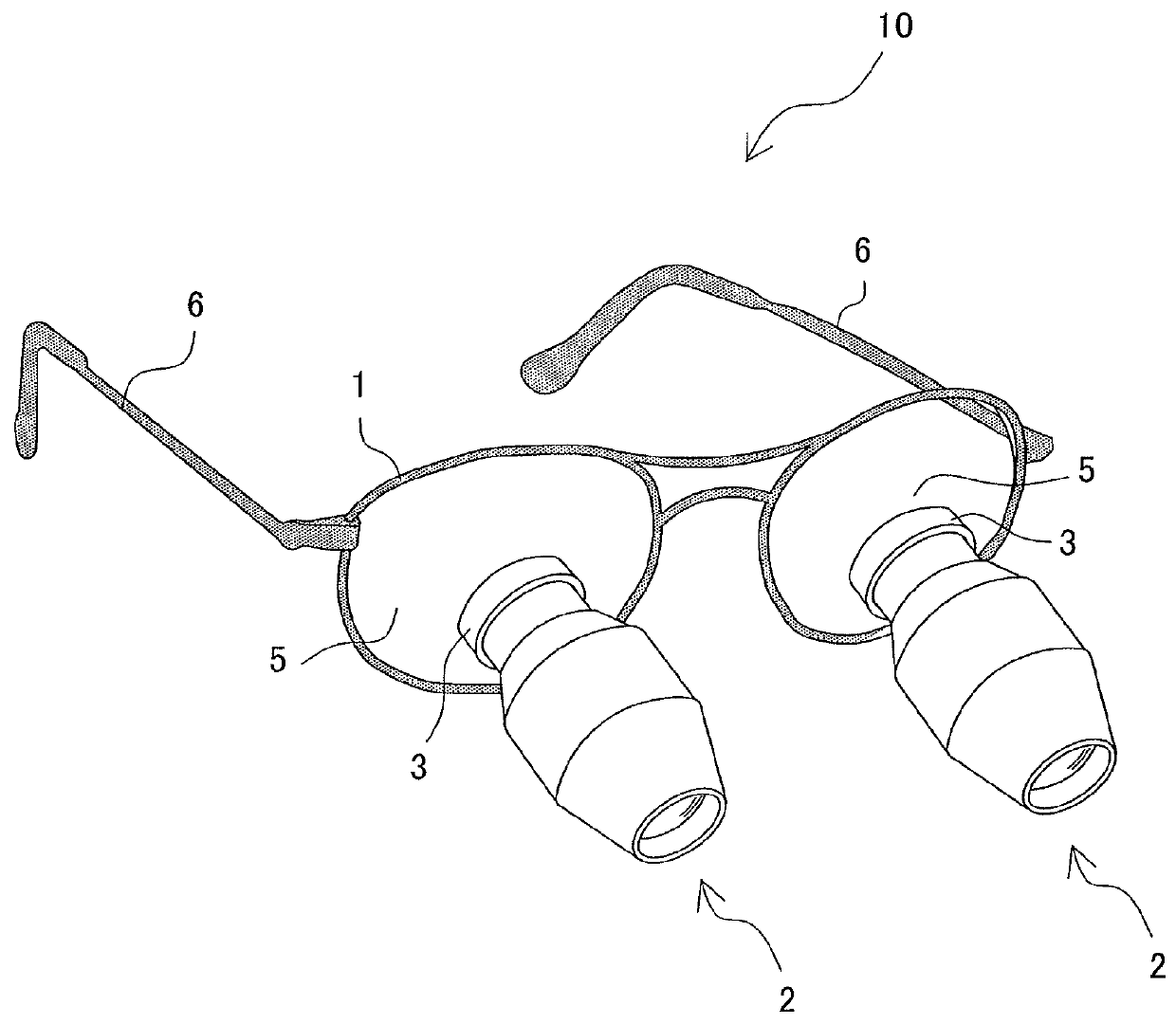
[0054]First, the present method for manufacturing a binocular loupe also starts with selecting a frame which fits to a head section and a face section of an operator.

(Specifying Pupil Position)

[0055]With the method for manufacturing a binocular loupe according to the present invention, an operator takes a working posture (see FIG. 4) in a state of wearing a frame 1 on which loupe units 2 are not mounted. Then, strobe light is radiated toward the face section of the operator from an operational manipulating position P at which the operator actually operates at hand and photographing is performed with a camera 11A (a first imaging device), so that pupil positions are specified.

[0056]Next, specifying of pupil positions using the camera 11A will be specifically described. FIG. 8 schematically illustrates a configuration of the camera 11A. The camera 11A is a digital camera including a control unit 12, a strobe light radiation device 13, an optical system 14, an imaging element 15, an im...

second embodiment

[0103]Next, a method to use an angular velocity sensor for obtaining the downward wearing angle will be described as another embodiment. For example, a gyro sensor may be adopted as the angular velocity sensor and is attached to the frame 1. Here, when an operator wearing the frame 1 takes a working posture, the gyro sensor outputs voltage corresponding to an inclination angle of the frame 1. The computer 20 calculates the downward wearing angle by performing arithmetic processing on a value of the output signal from the gyro sensor. In this case, the downward wearing angle obtained through the arithmetic processing is commonly used for the right and left. Here, owing to using the angular velocity sensor, the distance A and distance B are not required to be measured.

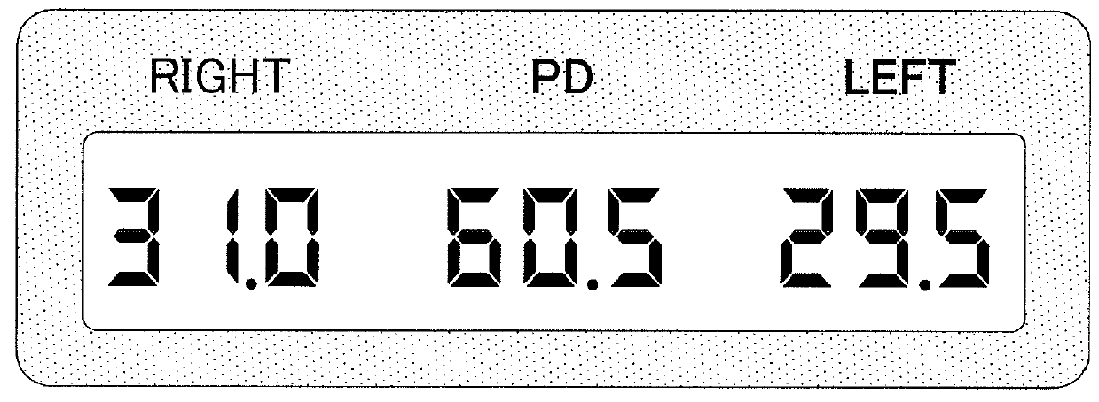
[0104]Then, opening portions are formed at the right and left carrier lenses 5 based on the right pupil position, the left pupil position, and the inward wearing angles p, q which are obtained with the same method as in ...


PUM


Abstract

Provided is a method for manufacturing a binocular loupe, the method including radiating strobe light from a below-located operational manipulating position in a state that the operator wearing the frame on which the carrier lenses are mounted stares the operational manipulating position in a working posture to use the binocular loupe, photographing reflection light of the strobe light reflected from pupils of the operator with a camera 11, specifying pupil positions based on the image data, and determining downward wearing angles r1, r2 of the loupe units which are to be attached to the right and left carrier lenses based on distance A from the operational manipulating position P to the carrier lenses and a horizontal distance B from the operational manipulating position P to a vertical line passing through the carrier lens.

Description

BACKGROUND OF THE INVENTION[0001]1. Field of the Invention[0002]The present invention relates to a binocular loupe which is used during medical surgery or precision machine operation, and in particular, relates to a method for manufacturing a binocular loupe in which loupe units are attached to carrier lenses in a frame.[0003]2. Description of Related Arts[0004]Conventionally, binocular loupes have been widely used as means to stare a target locally at hand in an enlarged manner in a variety of fields such as medical fields, precision machining, jewel processing, and the like. In such fields, it is required to be capable of staring with a high degree of accuracy.[0005]As illustrated in FIG. 1, a binocular loupe 10 being a general lens fitting type is configured to include a frame 1 having the same structure as glasses to correct eyesight of an operator, loupe units 2 being a binocular loupe main body for enlarging an image of an operational target, carrier lenses 5 to which the loup...

Claims


Application Information

Patent Timeline
Patent Type & Authority Patents(United States)
IPC IPC(8): A61B3/10G02B25/00G02C13/00A61B3/11G02C7/08
CPCG02C13/005A61B3/111G02B25/004G02C7/088A61B1/009
Inventor NAKAMURA, SHOICHI
Owner ACP JAPAN
Why Eureka
Try Eureka