
Physical downlink shared channel transmission method

a shared channel and transmission method technology, applied in the field of wireless communication systems, can solve the problems of inability to schedule in cross-carrier, grave adjacent channel interference, downlink subframes, etc., and achieve the effect of enhancing cross-carrier scheduling flexibility, increasing terminal user peak rate, and increasing terminal user throughpu

Active Publication Date: 2016-05-03
SAMSUNG ELECTRONICS CO LTD
View PDF11 Cites 0 Cited by
  • Summary
  • Abstract
  • Description
  • Claims
  • Application Information

AI Technical Summary

Benefits of technology

This approach increases the peak rate and satisfies the requirement for higher throughput by allowing more PDSCHs to be scheduled across different sub-frames, even when cells have different TDD configurations, reducing interference and improving system performance.

Problems solved by technology

At this point, if these cells continue to adopt the same TDD uplink and downlink configuration, serious adjacent channel interference will be generated.
Therefore, in subsequent studies of LTE-A, an important issue is how to effectively support the multiple cells on which Carrier Aggregation will be performed, wherein the multiple cells have different TDD uplink and downlink configurations.
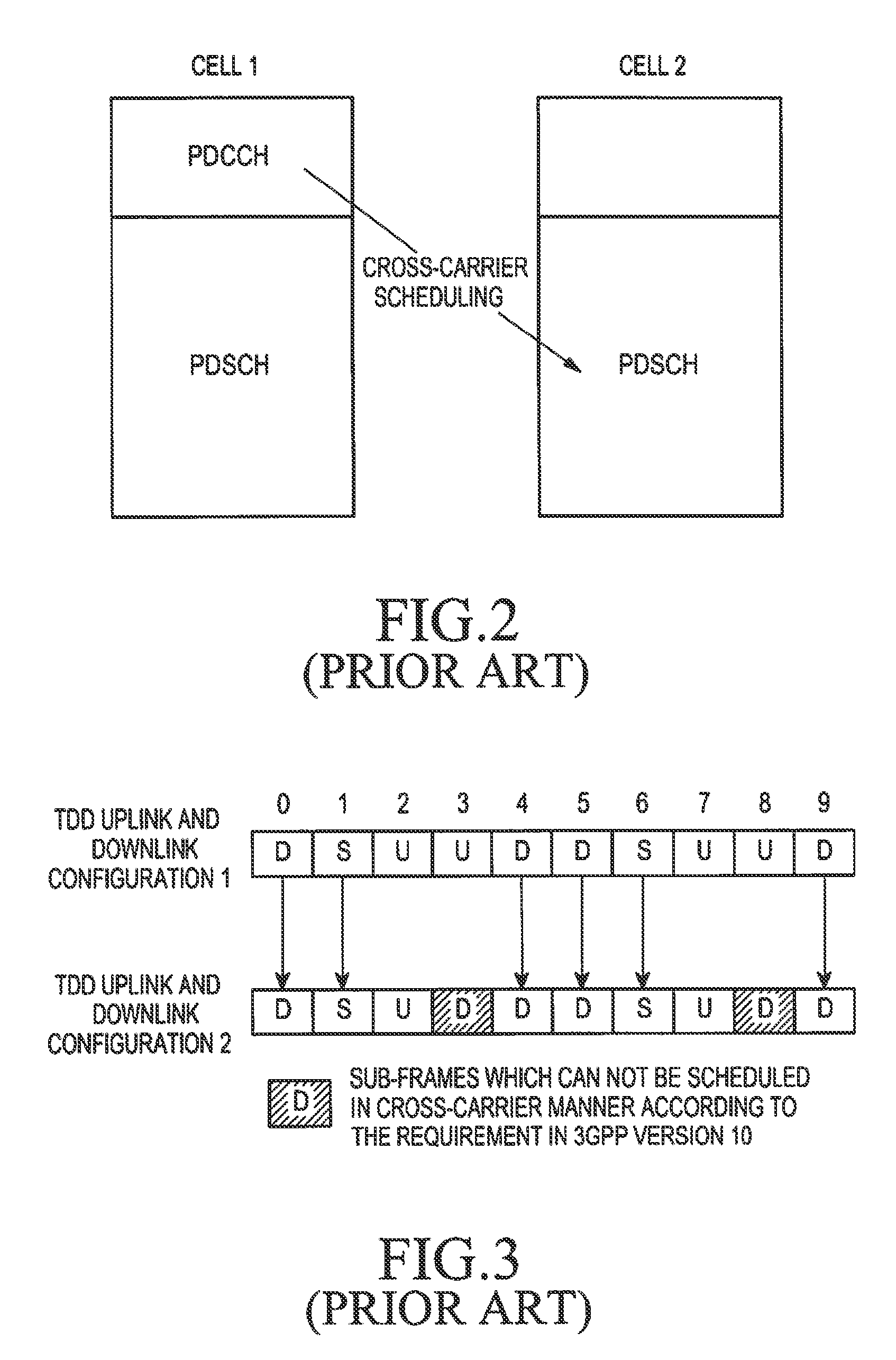
Thus, when the TDD uplink and downlink configuration of the cell for scheduling is different from that of the cell being scheduled, especially when the downlink sub-frames of the cell being scheduled is not in a set of downlink sub-frames of the cell for scheduling, PDSCHs in part of downlink sub-frames of the cell being scheduled will be unable to be scheduled in cross-carrier manner due to the TDD uplink and downlink configuration of the part of downlink sub-frames that is different from that of the downlink sub-frames of the cell for scheduling.
As can be seen, when the existing PDSCH cross-carrier scheduling method is adopted to implement the PDSCH transmission, it may cause a problem in that PDSCHs in part of the sub-frames can not be scheduled.
Thus, the peak rate of a terminal user is affected, and a requirement for higher throughput of the terminal user can not be satisfied.

Method used


Image

  • Physical downlink shared channel transmission method
  • Physical downlink shared channel transmission method
  • Physical downlink shared channel transmission method

Examples


Embodiment Construction

[0028]Hereinafter, various embodiments of the present invention will be described with reference to the accompanying drawings. In the following description of the present invention, a detailed description of known functions and configurations incorporated herein will be omitted when it may obscure the subject matter of the present invention.

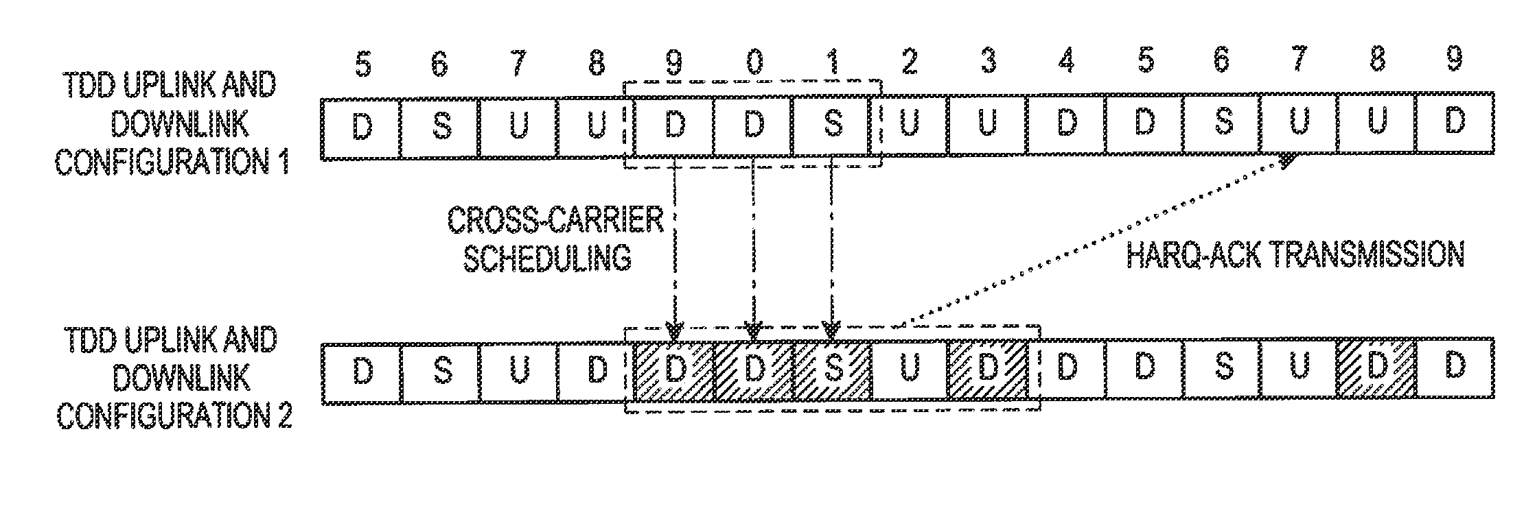
[0029]For a TDD system configured with carrier aggregation, in the present invention, TDD uplink and downlink configurations of multiple cells of a base station may be different. Similar to LTE-A, it is possible to configure a UE accessing the base station to work in at least one cell.

[0030]When sending cross-carrier scheduling information to a UE utilizing a PDCCH of a cell for scheduling, a base station also indicates a PDSCH of a cell being scheduled using the cross-carrier scheduling information, and the UE may determine PDSCH data in which sub-frames should be processed according to the indication. Thus, when cross-carrier scheduling is impl...


PUM


Abstract

A Physical Downlink Shared CHannel (PDSCH) transmission data method is provided. A User Equipment (UE) receives cross-carrier scheduling information in a PDCCH of a cell for scheduling. The cross-carrier scheduling information carries scheduling information indicating at least one PDSCH in at least one sub-frame of a cell being scheduled in cross-carrier scheduling. The UE processes data of PDSCH corresponding to the instruction according to received cross-carrier scheduling information. The UE sends a HARQ-ACK message to a base station according to the processed result. The peak rate of the UE is increased, and the requirement for higher throughput of the UE is satisfied.

Description

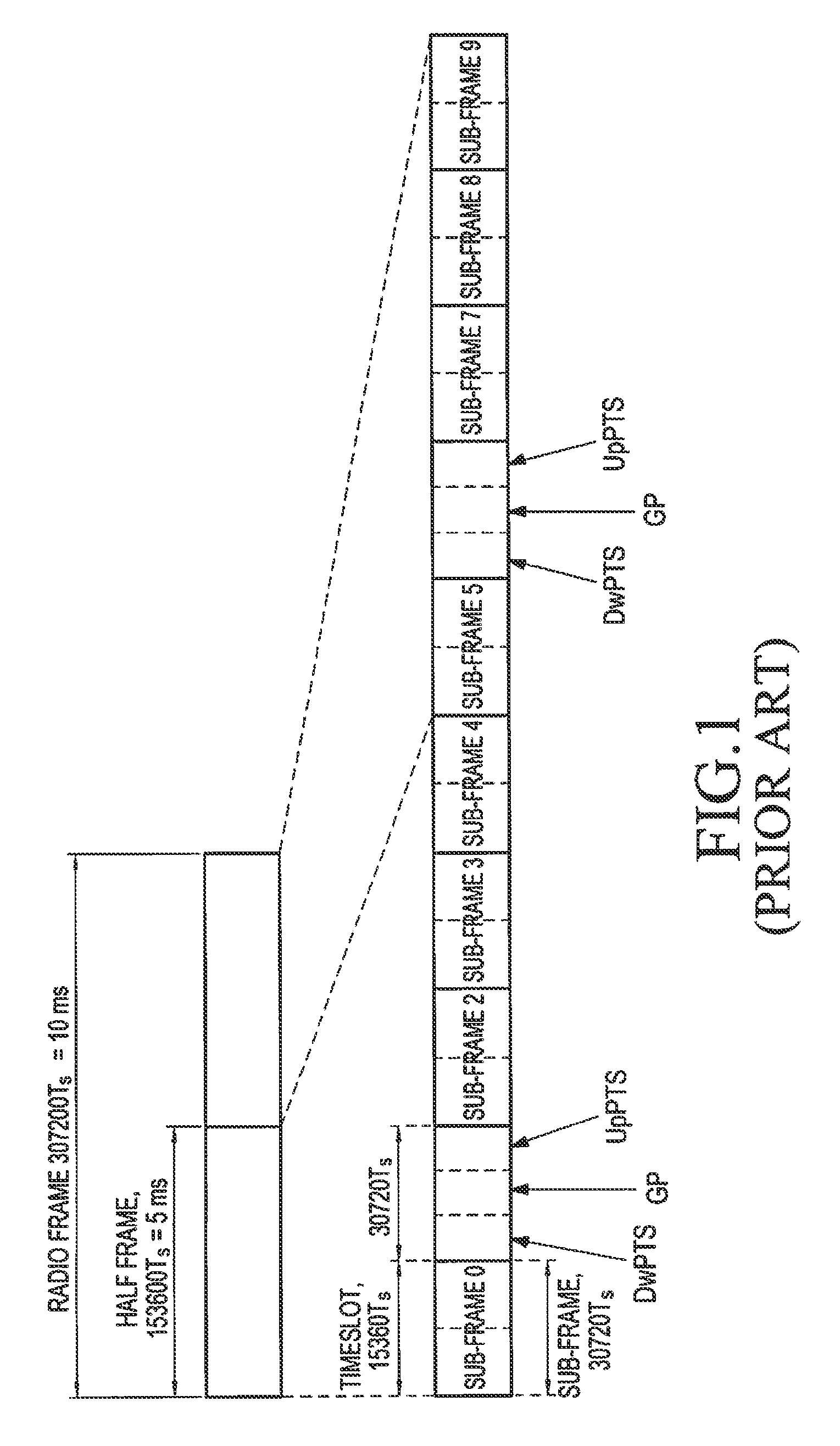
PRIORITY[0001]This application claims priority under 35 U.S.C. §119(a) to Chinese Application Serial No. 201210071047.8, which was filed in the Chinese Intellectual Property Office on Mar. 16, 2012, the entire content of which is incorporated herein by reference.BACKGROUND OF THE INVENTION[0002]1. Field of the Invention[0003]The present invention generally relates to wireless communication systems, and more particularly, to a Physical Downlink Shared CHannel (PDSCH) data transmission method.[0004]2. Description of the Related Art[0005]A Long Term Evolution (LTE) system supports a Frequency Division Duplexing (FDD) mode and a Time Division Duplexing (TDD) mode. FIG. 1 is a schematic diagram illustrating the structure of a frame in a TDD system. The length of each radio frame is 10 ms, with each radio frame divided into two half-frames of a length of 5 ms. Each half-frame consists of eight data time slots, each of which having a length of 0.5 ms, and three special time slots, i.e., Do...

Claims


Application Information

Patent Timeline
Patent Type & Authority Patents(United States)
IPC IPC(8): H04W72/04H04W72/12H04L1/18
CPCH04W72/04H04L1/1861H04L1/1864H04L1/1887H04W72/1273
Inventor FU, JINGXINGSUN, CHENGJUNLI, YINGYANG
Owner SAMSUNG ELECTRONICS CO LTD
Learn More