
Method and apparatus for tissue sampling

a tissue sampling and tissue technology, applied in the field of tissue sampling devices, can solve the problems of time-consuming and uncomfortable for patients, areas of the body arousing suspicion of being or becoming cancerous,

Active Publication Date: 2016-05-03
THE CLEVELAND CLINIC FOUND
View PDF16 Cites 169 Cited by
  • Summary
  • Abstract
  • Description
  • Claims
  • Application Information

AI Technical Summary

Problems solved by technology

Frequently, areas of the body may arouse suspicion as being or becoming cancerous due to a change in appearance, function, or physiology.
A problem with cutting tissue samples along a straight path is that multiple samples (passes) must be taken in the targeted area to obtain a sufficient tissue volume for diagnostic testing.
This can be both time consuming as well as uncomfortable for the patient, as acquiring multiple tissue samples requires multiple needle insertions.

Method used


Image

  • Method and apparatus for tissue sampling
  • Method and apparatus for tissue sampling
  • Method and apparatus for tissue sampling

Examples


Embodiment Construction

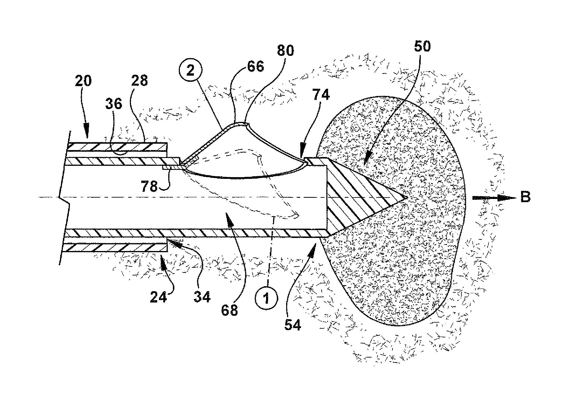
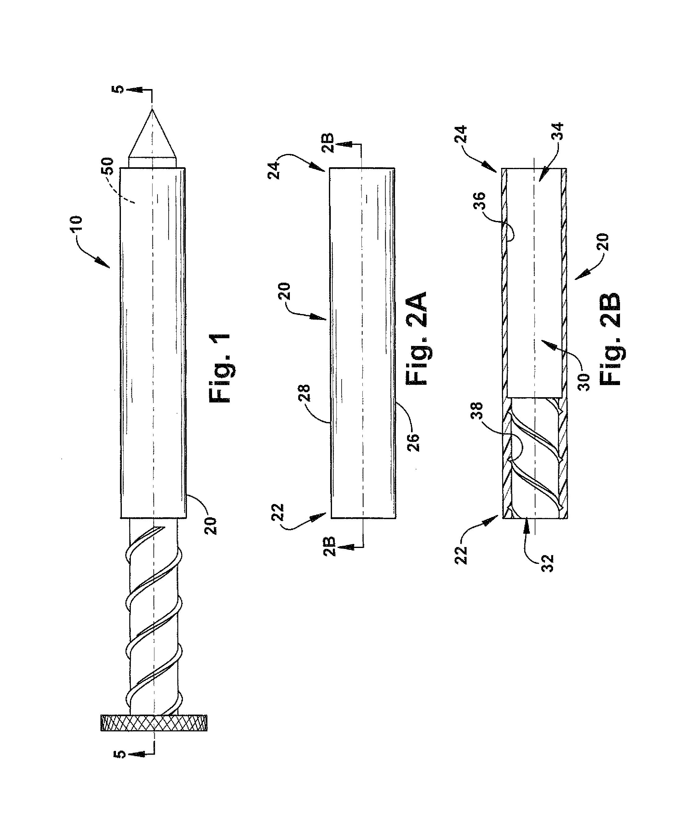
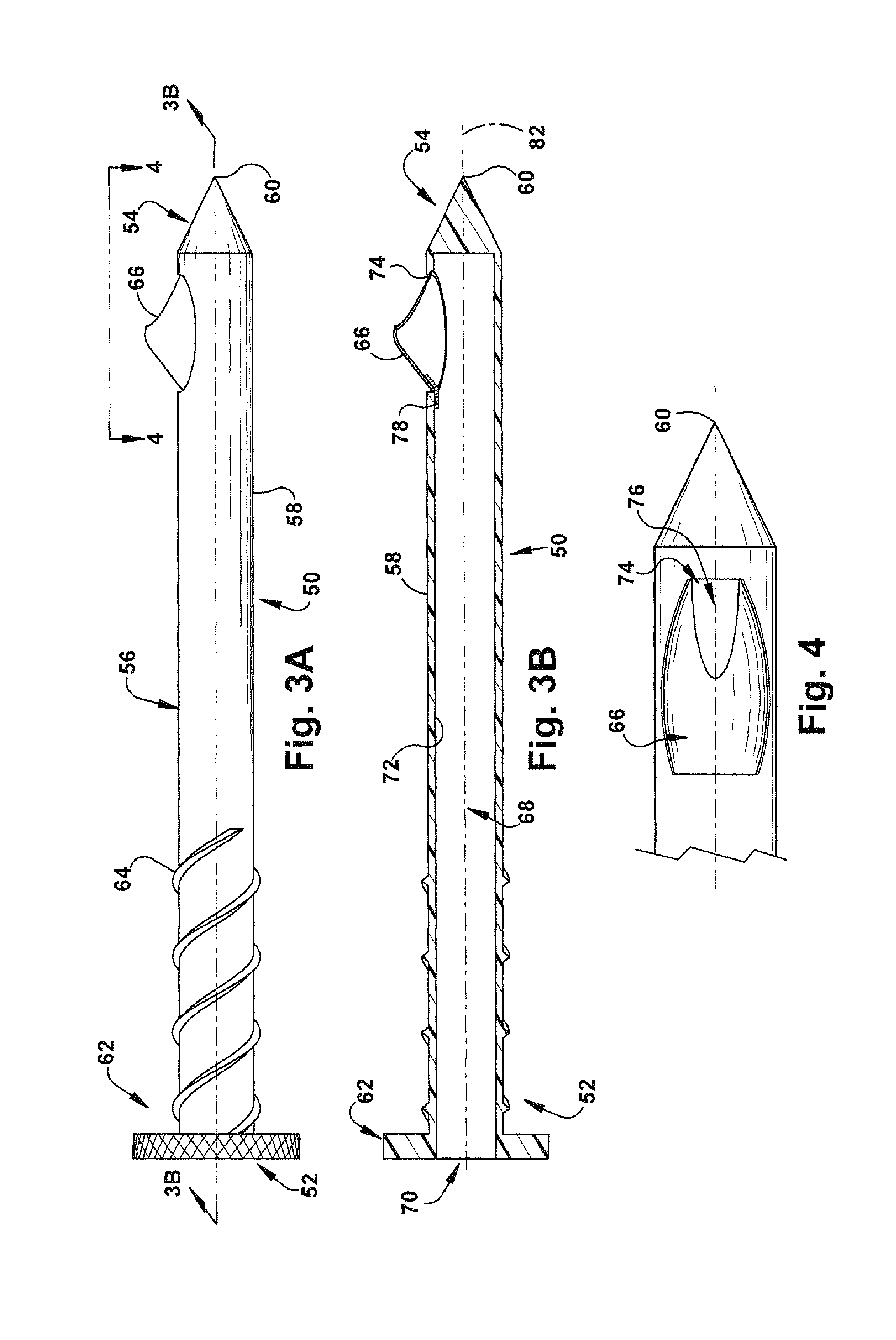
[0027]The present invention is directed to a tissue sampling device, and in particular, to a biopsy device that cuts tissue from a target area in the body along a helical path. As shown in FIG. 1, the device 10 includes an outer sheath 20 and a concentric inner tube 50. The sheath 20 has a proximal end 22, a distal end 24, and a body portion 26 extending between the proximal end and the distal end (FIG. 2A). The distal end 24 may be blunt or have an otherwise atraumatic construction. The sheath 20 further includes an outer surface 28 and a substantially concentric inner surface 36, thereby forming a generally tubular cross-section (FIG. 2B). Although the inner surface 36 and the outer surface 28 are illustrated as having circular cross-sections, those having ordinary skill will appreciate that the inner and outer surfaces can have alternative cross-sections, such as triangular, square or any other polygonal construction. The inner surface 36 defines a passage 30, which extends from ...


PUM


Abstract

A tissue sampling device includes a sheath having an inner surface having a proximal end and a distal end, and an inner surface defining a passage. An inner tube is disposed within the passage. The inner tube has an inner surface defining a passage, and an outer surface radially spaced outward from the inner surface. A cutting needle is pivotally mounted to the inner tube and pivots between a first position radially inward of the inner surface of the sheath and a second position substantially radially outward of the outer surface of the inner tube. Relative movement between the inner tube and the sheath causes the cutting needle to move between the first position and the second position. Rotation of the inner tube relative to the sheath when the cutting needle is in the second position causes the cutting needle to remove tissue in a helical path.

Description

RELATED APPLICATION[0001]This application claims priority from U.S. Provisional Application No. 60 / 989,268, filed Nov. 20, 2007, the subject matter of which is incorporated herein by reference.GOVERNMENT RIGHTS[0002]The invention described in this application was supported, at least in part, by United States Government Contract No. W81XWH-05-1-0564 with the United States Department of Defense Telemedicine and Advanced Technology Research Center (TATRC) and, thus, the United States government may have certain rights in the invention.TECHNICAL FIELD[0003]The present invention is directed to a tissue sampling device, and in particular, to a biopsy device that cuts tissue from a target area in the body along a helical path.BACKGROUND OF THE INVENTION[0004]Cancer is one of the leading causes of death in the United States. Several hundred thousand individuals die as a result of some form of cancer. Therefore, the need to diagnose and treat cancerous or otherwise harmful lesions at the ear...

Claims


Application Information

Patent Timeline
Patent Type & Authority Patents(United States)
IPC IPC(8): A61B10/02A61B17/3205A61B17/34A61B17/32A61B17/3207
CPCA61B10/0275A61B10/0266A61B10/0283A61B17/32053A61B2010/0208A61B2017/32004A61B2017/320791A61B2017/3409A61B2090/035A61B2090/062
Inventor POLSTER, JOSHUA M.
Owner THE CLEVELAND CLINIC FOUND
Learn More