
System and methods for world-scale camera pose estimation

a world-scale, camera-based technology, applied in the field of computer vision systems, can solve the problems of reducing affecting the accuracy of camera-based pose estimation, and coarse location

Active Publication Date: 2016-04-26
CORNELL UNIV CENT FOR TECH LICENSING CTL AT CORNELL UNIV
View PDF10 Cites 6 Cited by
  • Summary
  • Abstract
  • Description
  • Claims
  • Application Information

AI Technical Summary

Benefits of technology

[0019]One advantage of the present invention includes photo browsing and organization. It is contemplated that the present invention can automatically geographically tag photos in various photo collections, as well as automatically tag photos with the objects in the field of view—e.g., “Statute of Liberty” or “Times Square”—based on the accurate location or orientation computed for the photo. Advantageously, this works even if the photo does not have GPS, or if the GPS is inaccurate.
[0020]Another advantage of the present invention includes augmented reality and navigation. Applications that require augmenting photos with annotations or other information or for providing navigational instructions often require very accurate (“pixel accurate”) geo-registration. GPS is often too coarse an estimate of location for this kind of task.
[0021]Another advantage of the present invention includes intelligence and forensics. Military and law enforcement agencies often deal with photos from uncooperative sources, for example, from hard drives or cameras captured in the field. Extracting intelligence or other information from these images is often of critical importance. The present invention accommodates such uncontrolled imagery.

Problems solved by technology

Localizing where a photo or video was taken is a key problem in computer vision, with a broad range of applications in consumer photography, augmented reality, photo editing, autonomous and human navigation, and forensics.
In other related work, human travel priors are used to improve performance for sequences of images, but the resulting locations remain fairly coarse.
Thus, it become less effective when as the size of the model grows.
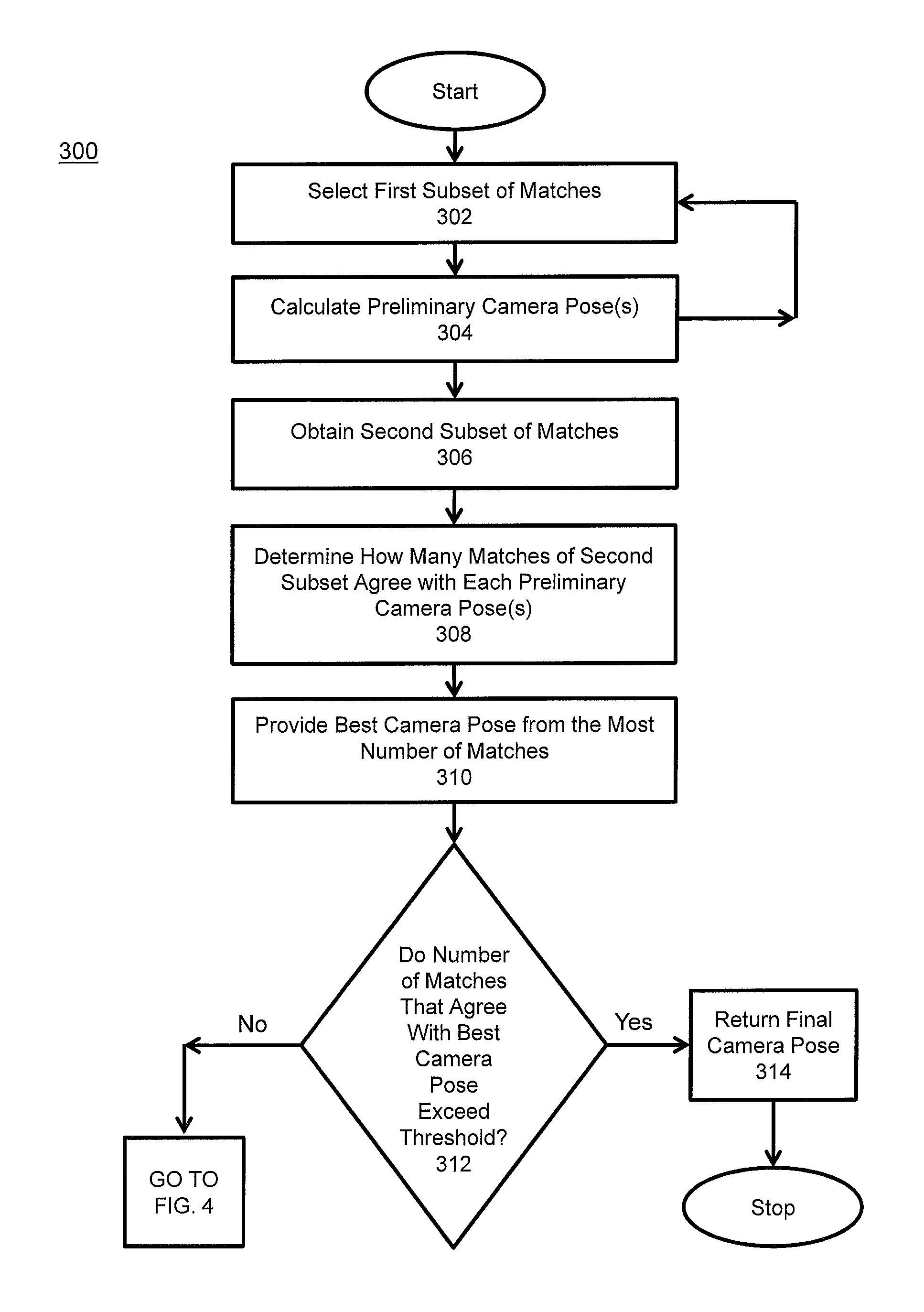
However, the accuracy of camera pose estimation may decrease since it results in a smaller set of matches.
Moreover, the set of matches obtained in this way is often noisy enough such that RANdom SAmple Consensus (RANSAC) needs to be run for up to one minute.

Method used


Image

  • System and methods for world-scale camera pose estimation
  • System and methods for world-scale camera pose estimation
  • System and methods for world-scale camera pose estimation

Examples


Embodiment Construction

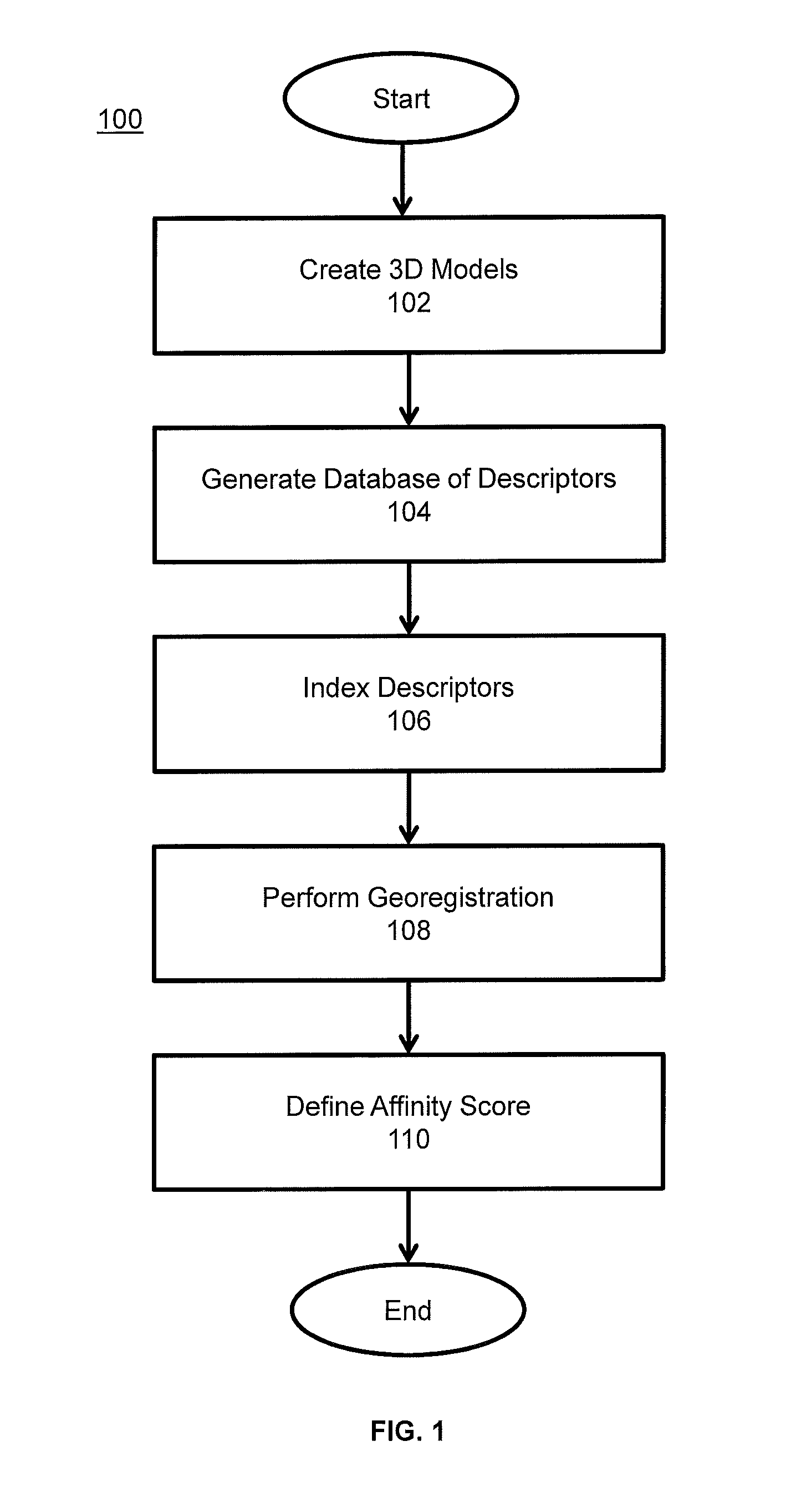
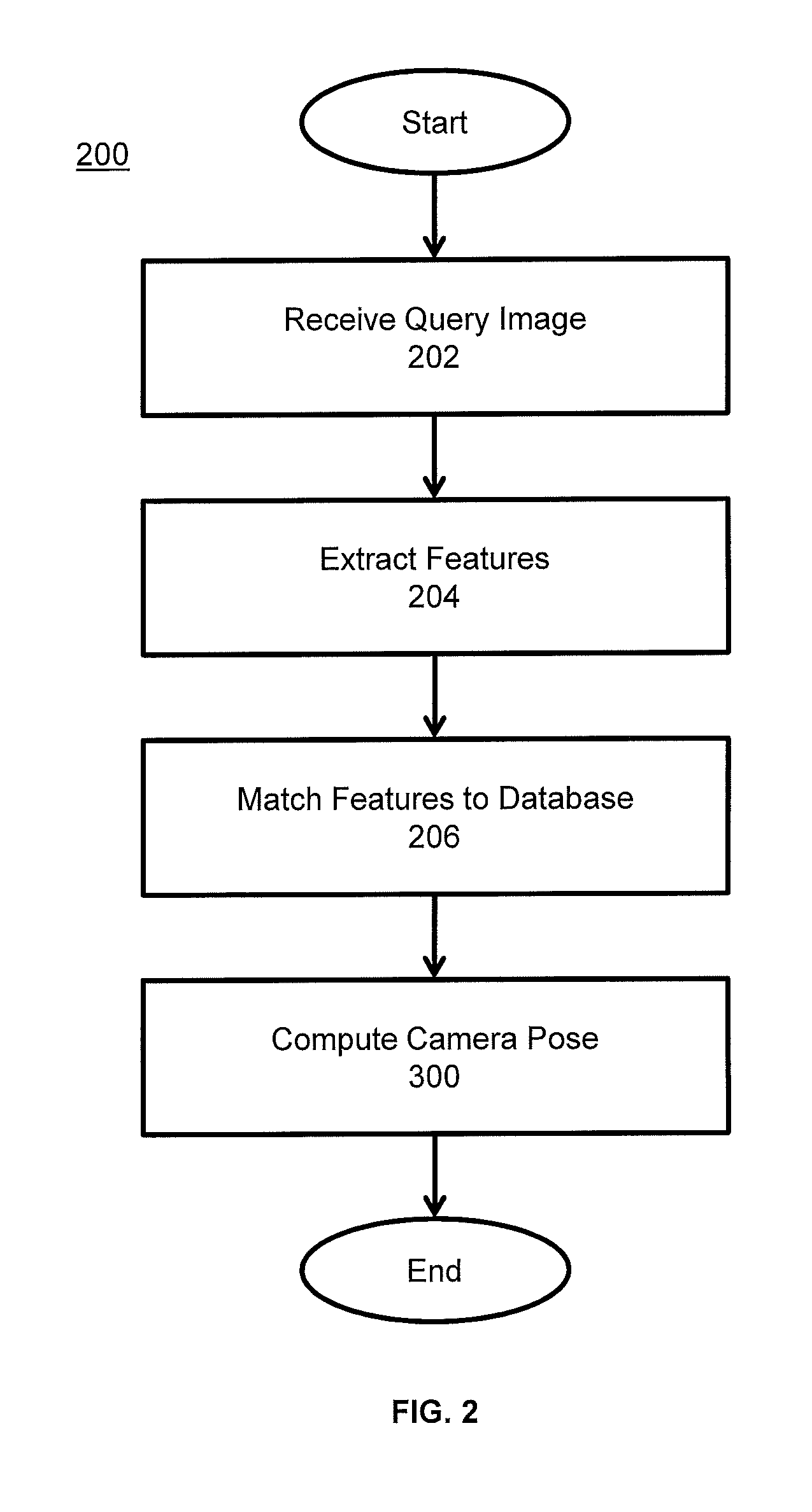
[0028]The present invention occurs in two stages: (1) a database construction stage, performed offline, and (2) an image-to-database matching and camera-pose-estimation stage, performed at runtime. The database construction stage results in a database of 3D features and associated feature descriptors.

[0029]Specifically, the database construction stage takes as input a large set of images with “geotags”. “Geotags” are annotations of latitude and longitude. The images are grouped into subsets corresponding to different landmarks, and a database comprised of one or more points (referred to as points in the database or database points)—such as 3D points—is constructed along with one or more associated feature descriptors for each point in the database.

[0030]The database is used in the image-to-database matching and camera-pose-estimation stage to provide the location or orientation in the world for an input image. Specifically, a query image is matched to the database and the camera pos...


PUM


Abstract

System and methods for determining where a digital photograph was taken by estimating the camera pose with respect to a global scale three-dimensional database. Accurate location and orientation of the digital photograph is established through feature correspondence and geometry estimated from photograph collections.

Description

PRIORITY CLAIM[0001]This application claims the benefit of U.S. Provisional Application No. 61 / 568,183 filed Dec. 8, 2011.STATEMENT CONCERNING U.S. GOVERNMENT SPONSORED RESEARCH[0002]This invention was made with U.S. government support under grants IIS-0964027 and IIS-0713185 awarded by the National Science Foundation (NSF). The U.S. government has certain rights in the invention.FIELD OF THE INVENTION[0003]The present invention relates generally to computer vision systems. More specifically, the present invention relates to estimating the location or the orientation of a digital photograph in order to know exactly where on the Earth's surface a particular photograph was taken, which direction the photo is oriented, as well as other parameters, such as the zoom level of the photo.[0004]Knowing exactly where a photograph was taken and how it was oriented may be useful in a variety of applications, including, for example, photo browsing and organization, augmented reality and navigati...

Claims


Application Information

Patent Timeline
Patent Type & Authority Patents(United States)
IPC IPC(8): G06T7/00G06F17/30G06K9/00
CPCG06T7/0044G06F17/30247G06K9/00664G06T7/0046G06T2200/04G06T2207/30244G06T7/74G06T7/75G06F16/583G06V20/10
Inventor SNAVELY, NOAHHUTTENLOCHER, DANIELLI, YUNGPENG
Owner CORNELL UNIV CENT FOR TECH LICENSING CTL AT CORNELL UNIV
Learn More