
Method and apparatus for estimating queuing delay

a technology of delay estimation and queuing delay, applied in electrical equipment, digital transmission, data switching networks, etc., can solve problems such as significant forward ott measurement error, affecting the service quality of applications, and skew between clocks, so as to reduce possible errors in estimation and minimize errors

Active Publication Date: 2016-04-05
SAMSUNG SDS CO LTD
View PDF6 Cites 0 Cited by
  • Summary
  • Abstract
  • Description
  • Claims
  • Application Information

AI Technical Summary

Benefits of technology

The patent text describes a mechanism for estimating the delay in queuing packets of data. This is done by measuring the time it takes for a packet to travel forward and backward through a network. By measuring these times and updating them to account for any errors caused by clock skew, the mechanism reduces the errors in the estimate of the queuing delay. This approach requires fewer measurements and provides a more accurate estimate of the delay for each measurement point. Overall, the mechanism improves the accuracy of queuing delay estimation.

Problems solved by technology

One of the major causes of errors in the forward OTT measurement is a clock skew between the clock of the transmitter and the clock of the receiver.
Such difference may cause a significant error in the forward OTT measurement.
In particular, when the computer network is used for a real time application such as Voice-over-IP or Video-over-IP, the incorrectly estimated value of the forward queuing delay may hamper the task of fulfilling a service quality demand of the application.
A clock skew may not be a source of errors in RTT measurement, but may cause errors in OTT measurement (for example, errors in forward OTT measurement).
This type of algorithm, which should take a large number of samples collected over a considerable period of time, has a high complexity of, e.g., O(N2).
In addition, the algorithm is difficult to apply to real time data transmission.
Furthermore, even if, at a certain time point, the calculated absolute value of the clock skew slightly deviates from the actual one thereof, such deviation may cause great errors in estimating a queuing delay after the time point, and therefore poor performance in transmission control.

Method used


Image

  • Method and apparatus for estimating queuing delay
  • Method and apparatus for estimating queuing delay
  • Method and apparatus for estimating queuing delay

Examples


Embodiment Construction

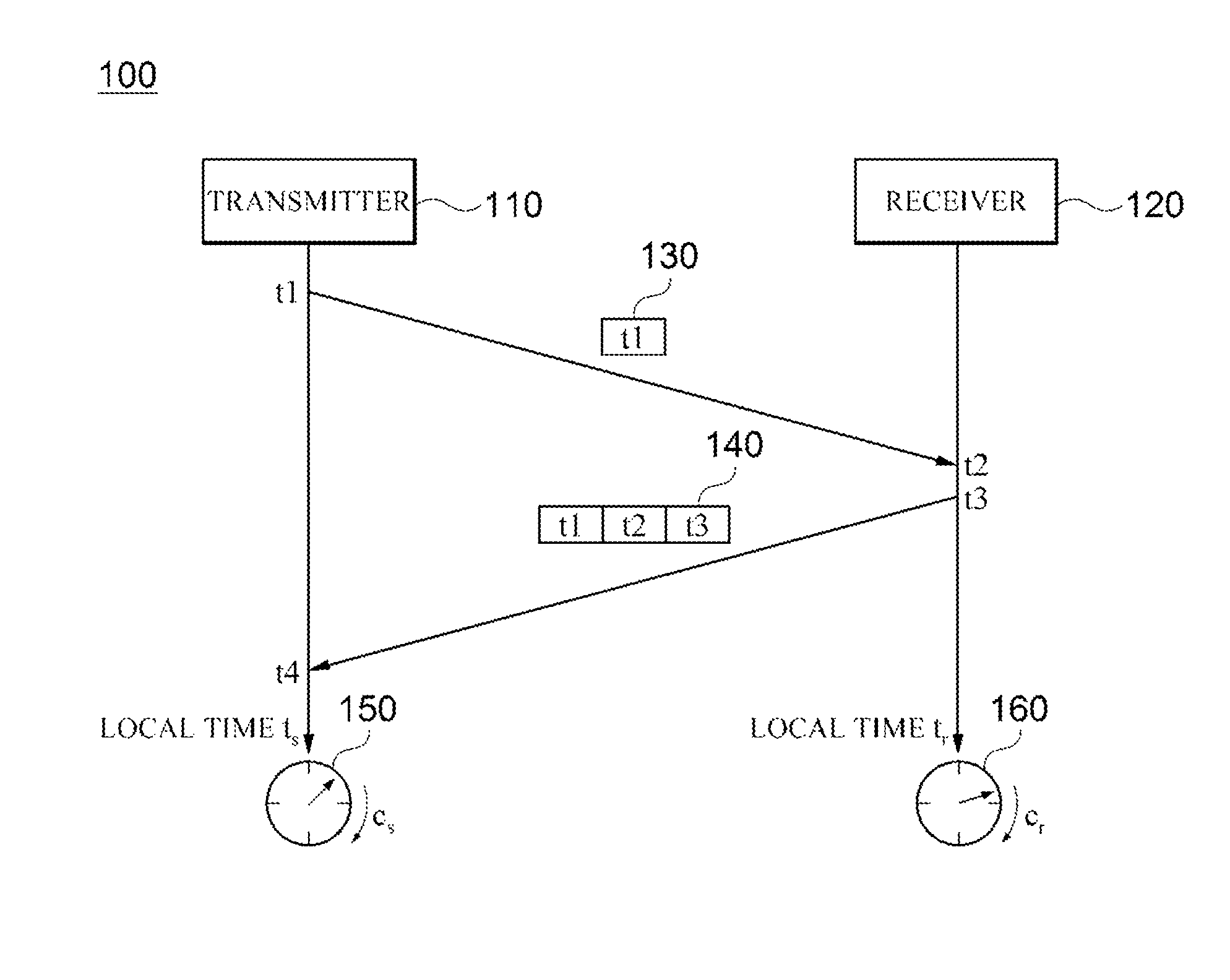
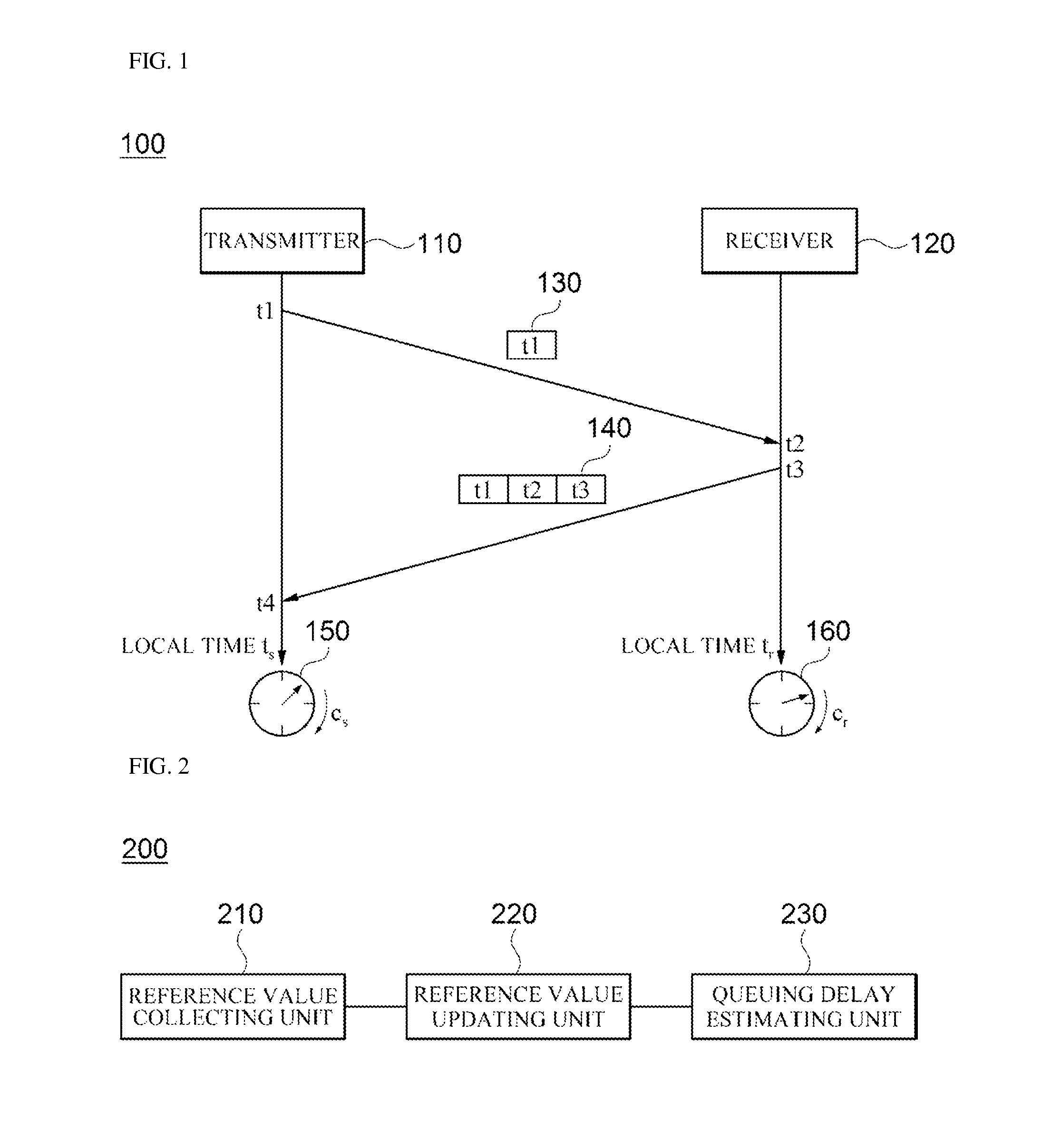
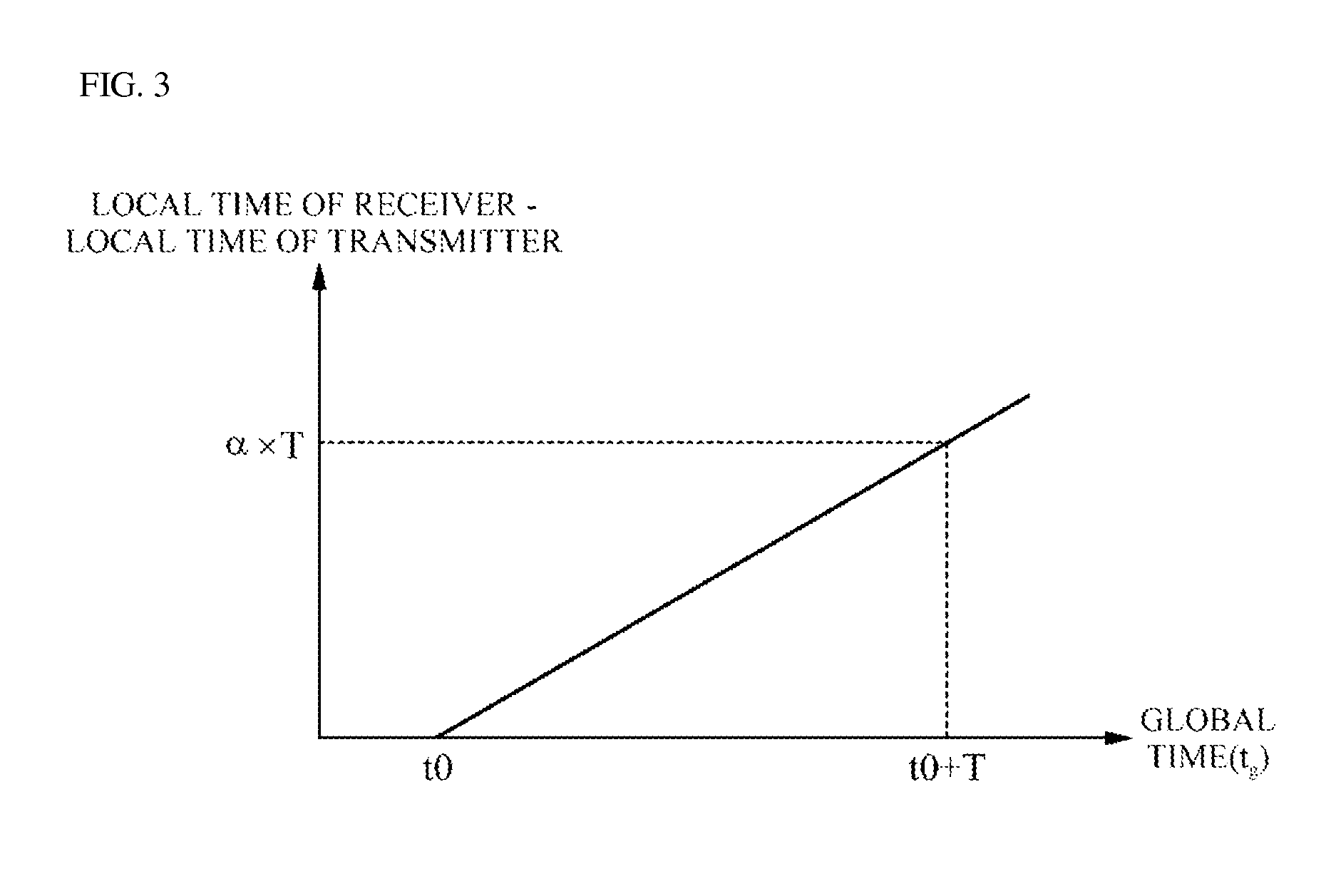
[0048]Exemplary embodiments of the present disclosure will be described below in more detail with reference to the accompanying drawings. The following detailed descriptions are provided to assist the reader in gaining a comprehensive understanding of the methods, apparatuses, and / or systems described herein. However, the embodiments are merely examples and are not to be construed as limiting the present disclosure.

[0049]Various details already understood by those familiar with this field may be omitted to avoid obscuring the gist of the present disclosure. Terminology described below is defined considering functions in the present disclosure and may vary according to a user's or operator's intention or usual practice. Thus, the meanings of the terminology should be interpreted based on the overall context of the present specification. The terminology used in the description is intended to describe embodiments of the present disclosure only, and shall by no means be restrictive. Unl...


PUM


Abstract

Provided is a method of estimating a queuing delay. The method includes: obtaining a round trip time (RTT) reference value, a forward one-way transmit time (OTT) reference value and a backward OTT reference value; and in accordance with a determination of whether a first increment rate is larger or smaller than a second increment rate, updating one of the forward OTT reference value and the backward OTT reference value based on the RTT reference value, the first increment rate being a rate of increment in local time of the transmitter, the second increment rate being a rate of increment in local time of the receiver.

Description

CROSS-REFERENCE TO RELATED APPLICATION[0001]This application claims priority to and the benefit of Republic of Korea Patent Application No. 10-2013-0129990, filed on Oct. 30, 2013, the disclosure of which is incorporated herein by reference in its entirety.BACKGROUND[0002]1. Field[0003]The present disclosure relates to data transmission control, and more particularly, to techniques for reducing errors in queuing delay estimation caused by a clock skew, thereby providing improved data transmission control.[0004]2. Discussion of Related Art[0005]A computer network may include several computing devices for exchanging data through a communication path. In such a computer network, a computing device, when transmitting data to another computing device, may perform data transmission control based on a queuing delay involved in the data transmission. For example, in a network environment in which a data packet is transmitted via a router on a communication path, a queuing delay may be defin...

Claims


Application Information

Patent Timeline
Patent Type & Authority Patents(United States)
IPC IPC(8): H04L12/26H04L12/24
CPCH04L41/147H04L43/0858H04L43/0864H04L47/28
Inventor HWANG, JIN BUMLEE, CHANG HOONMO, HYUNG JOO
Owner SAMSUNG SDS CO LTD
Learn More