
Tire and wheel lift

a pneumatic tire and wheel technology, applied in the direction of wheel mounting apparatus, instruments, static/dynamic balance measurement, etc., can solve problems such as back injuries

Active Publication Date: 2016-04-05
QUALITY STAINLESS PRODS
View PDF38 Cites 8 Cited by
  • Summary
  • Abstract
  • Description
  • Claims
  • Application Information

AI Technical Summary

Benefits of technology

The present invention provides a trolley for use in a lift that can resist bending moments, including lateral bending moments and forward bending moments. The trolley has an elongated platform with upper and lower trolley wheels mounted on wheel axles on the rear face and upper and lower spacer wheels mounted on spacer axles perpendicular to the bottom face of the platform. The trolley can be attached to a lifting cradle and is designed to make a safe and stable connection during use. The technical effects of the invention include providing a compact and versatile trolley for use in various lift systems and ensuring safe and stable attachment of the lifting cradle.

Problems solved by technology

Although raising the vehicle may provide better access to the vehicle during many maintenance procedures, manual removal of a tire / wheel combination exceeding fifty pounds or more may result in back injury, particularly with repetitive lifting of such tire / wheel combinations as will occur in shop.

Method used


Image

  • Tire and wheel lift
  • Tire and wheel lift
  • Tire and wheel lift

Examples


Embodiment Construction

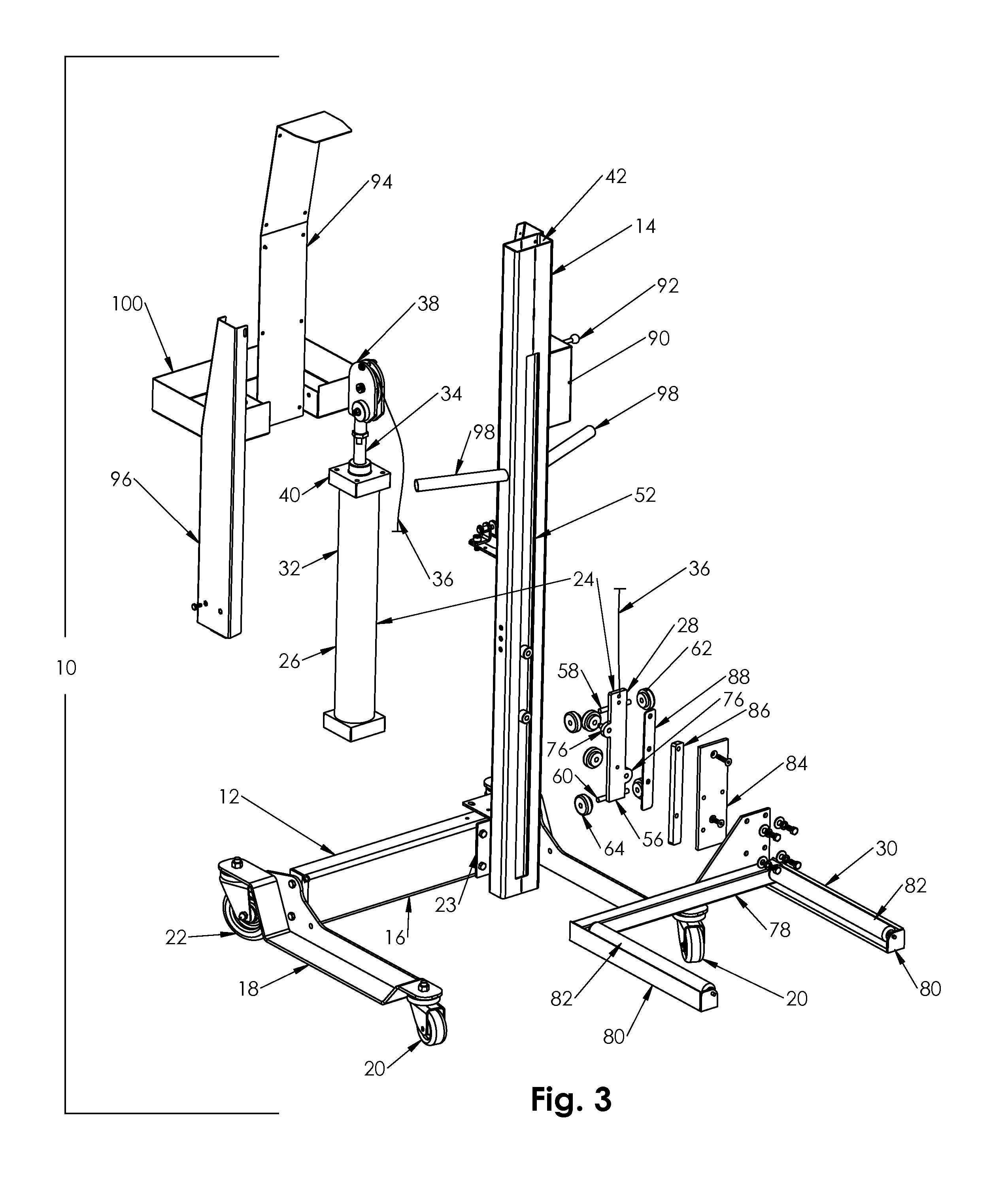
[0018]The following detailed description is merely exemplary in nature and is not intended to limit the described embodiments or the application and uses of the described embodiments. As used herein, the word “exemplary” or “illustrative” means “serving as an example, instance, or illustration.” Any implementation described herein as “exemplary” or “illustrative” is not necessarily to be construed as preferred or advantageous over other implementations. All of the implementations described below are exemplary implementations provided to enable persons skilled in the art to make or use the embodiments of the disclosure and are not intended to limit the scope of the disclosure, which is defined by the claims. For purposes of description herein, the terms “upper,”“lower,”“left,”“rear,”“right,”“front,”“vertical,”“horizontal,” and derivatives thereof shall relate to the invention as oriented in FIG. 1. Furthermore, there is no intention to be bound by any expressed or implied theory pres...


PUM


Abstract

A trolley for use in a cable lift having a mast with a generally rectangular hollow cavity forming a track in which the trolley may be reciprocated upwardly and downwardly. The trolley is connected to a cradle outside the mast upon which an object to be lifted may be placed. The trolley has trolley wheels which make rolling contact with a front and back side of the track to resist a forward bending moment in down direction on the cradle. The trolley has spacer wheels which make rolling contact with a right and left sides of the track to resist a lateral bending moment on the cradle such that the cradle may be mounted on the mast offset from centerline.

Description

BACKGROUND OF THE INVENTION[0001]1. Field of the Invention[0002]The present invention relates to a pneumatic tire and wheel lift wherein the mast is offset from the lifting forks for full access to lug nuts and easy and quick use with a wheel balancer or tire changer, for example. The invention further relates to a trolley for use with the tire and wheel lift as well as other cable lifts.[0003]2. Brief Description of the Prior Art[0004]Removal of a tire / wheel combination for repair from a passenger car, light / medium duty truck and SUV usually occurs after the vehicle has been raised several feet off the ground by a vehicle lift. Although raising the vehicle may provide better access to the vehicle during many maintenance procedures, manual removal of a tire / wheel combination exceeding fifty pounds or more may result in back injury, particularly with repetitive lifting of such tire / wheel combinations as will occur in shop. Employers and employees are concerned about this exposure to ...

Claims


Application Information

Patent Timeline
Patent Type & Authority Patents(United States)
IPC IPC(8): B60B30/10
CPCB60B30/10B60B2340/70B60B30/02B60B2900/311
Inventor PIERCE, PETER J.ALTNETHER, PAUL J.
Owner QUALITY STAINLESS PRODS
Learn More