
Method for compensating a failing nozzle

a nozzle and nozzle technology, applied in the field of compensating a failing nozzle, can solve the problems of undercompensation of linear defects or light lines in printed images, ineffective addition of colorants in providing additional optical density, and low probability of additional colorants overlapping other applied colorants, etc., to achieve the effect of little or no additional optical density, and high probability of addition of colorants

Active Publication Date: 2016-04-05
OCE TECH
View PDF8 Cites 7 Cited by
  • Summary
  • Abstract
  • Description
  • Claims
  • Application Information

AI Technical Summary

Benefits of technology

This approach reduces undercompensation and overcompensation, improving the uniformity of optical density in printed images by dynamically adjusting compensation based on environmental conditions and nozzle performance.

Problems solved by technology

A failing nozzle leads locally to a density deficit due to a shortage of colorant, since the failing nozzle does not apply an ink drop or is controlled not to apply an ink drop.
However, if this density deficit is filled up with colorant according to a fixed mechanism for compensating the failing nozzle, in some cases the compensation will be too large, leading to an overcompensated linear defect or a dark line in the printed image, and in other cases the compensation will be too small, leading to an undercompensated linear defect or a light line in the printed image.
Of course, there are also situations in which the compensation according to a fixed method is sufficiently redressing the deficit, but this is accidental and not structural.
Thus, the additional colorant is not effective in providing additional optical density.
However, it is prudent to apply this latter compensation mechanism only when the environment density is very large, since for low environment density, it may easily produce overcompensation.

Method used


Image

  • Method for compensating a failing nozzle
  • Method for compensating a failing nozzle
  • Method for compensating a failing nozzle

Examples


Embodiment Construction

[0023]The present invention will now be described with reference to the accompanying drawings, wherein the same or similar elements are identified with the same reference numeral.

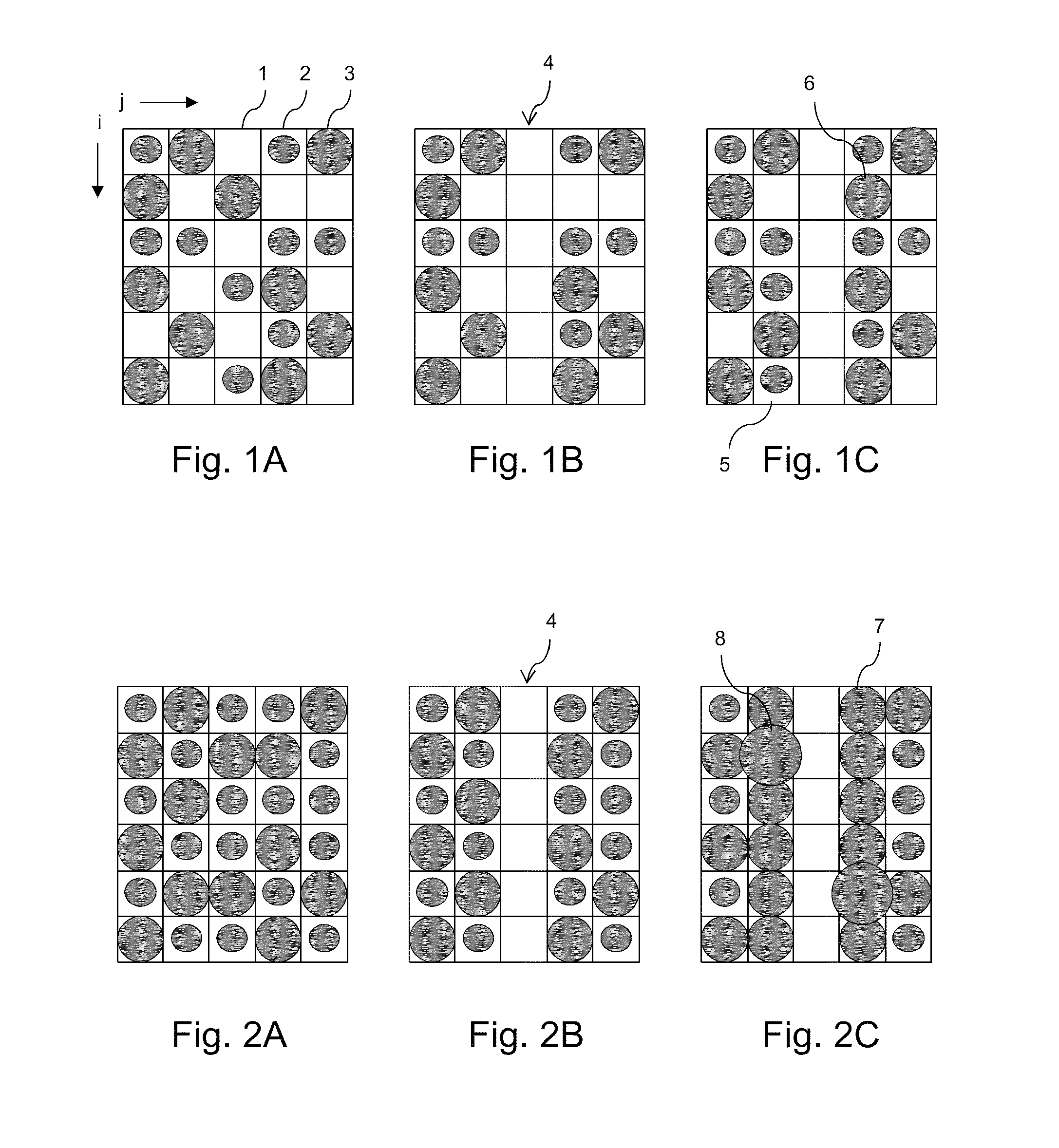
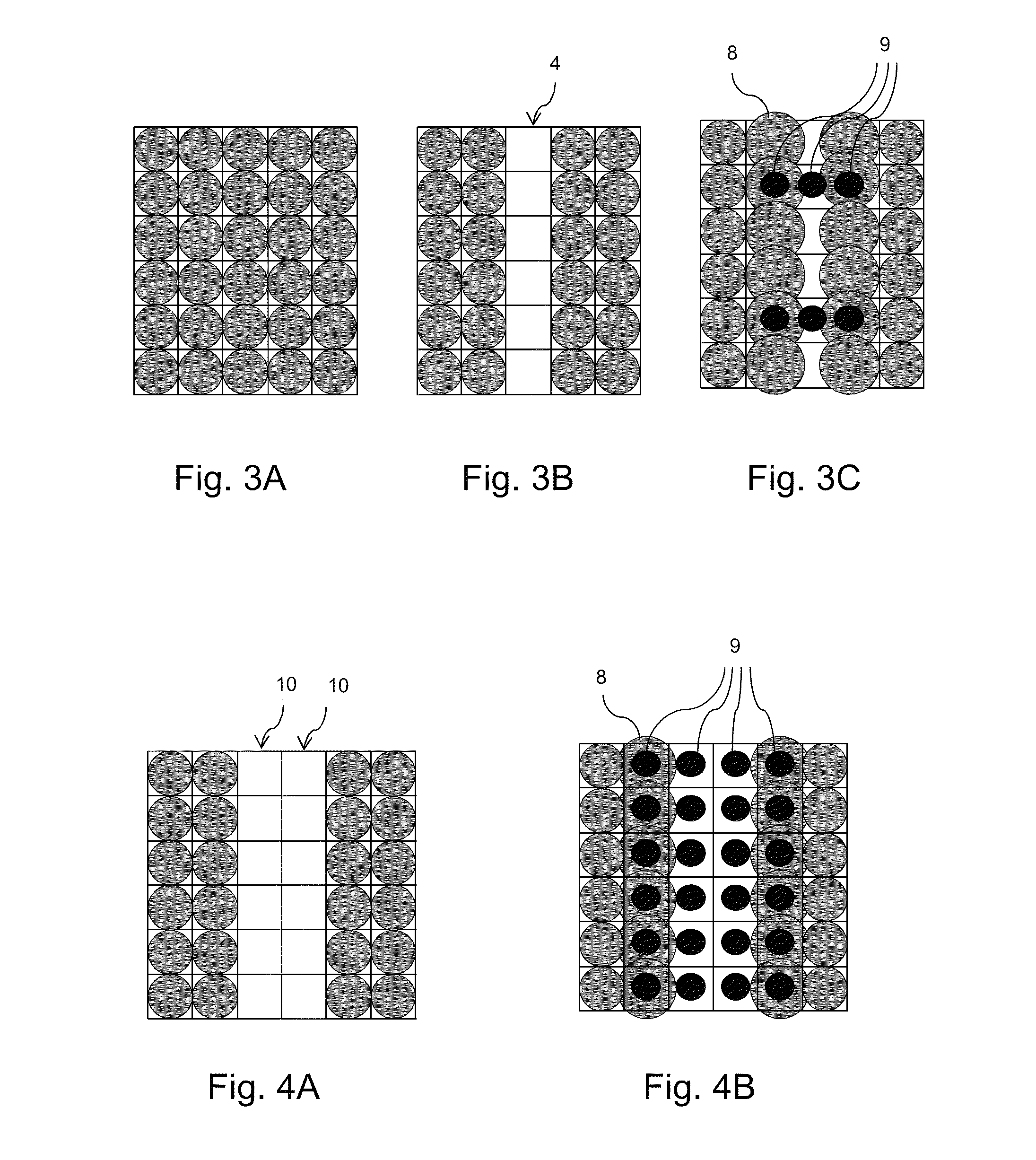
[0024]FIG. 1A shows an arrangement of dots that is intended to be produced by an inkjet printer. In this example, two different dot sizes are applied, but this is not essential in the present invention. A larger number of dot sizes is possible, but also a single dot size may be applied. The positions on a receiving medium where a dot may be applied, are often referenced as print pixels. The lines between the print pixels are a guidance for the eye only and are not part of the image as printed. In FIG. 1A, print pixel 1 does not receive a dot, print pixel 2 receives a small dot and print pixel 3 a large dot. The size of the dots is not necessarily limited to the print pixel area, as shown in FIG. 1A, but may just as well extend across the print pixel boundaries. The print pixels are arranged in rows, labeled...


PUM


Abstract

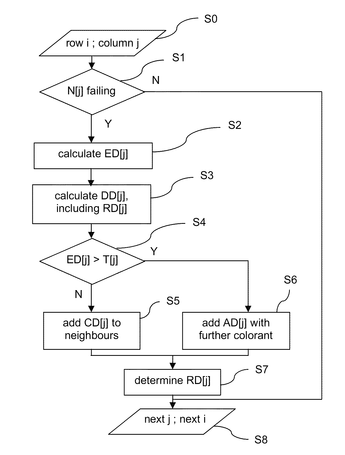
A method is provided for compensating a failing nozzle in a printhead comprising a series of print elements with nozzles for operation in an inkjet printing process in which a colorant is applied for locally changing an optical density, thereby printing an image. The method comprises at least two compensation mechanisms, each providing a different amount of additional optical density in the environment of a missing dot in the printed image. A nozzle is recorded as a failing nozzle if the associated print element does not apply an ink dot within predetermined specifications. An environment density is determined in an environment of a missing dot associated with said failing nozzle. The environment density is compared with a predetermined threshold, and an appropriate compensation mechanism is selected from the at least two compensation mechanisms. The method is applied in an inkjet printing system for balancing under- and overcompensated optical density.

Description

BACKGROUND OF THE INVENTION[0001]1. Field of the Invention[0002]The present invention relates to a method for compensating a failing nozzle in a printhead comprising a series of print elements for operation in an inkjet printing process in which a colorant is applied to a receiving medium for locally changing an optical density, thereby printing an image. The invention further relates to an inkjet printing system comprising control means configured to apply the invented method.[0003]2. Description of the Related Art[0004]Inkjet printing systems are getting increasingly sophisticated. Additional features relating to speed and print quality are continuously introduced for enhancing the range of applicability of inkjet printing systems. Furthermore, the printheads, that form the heart of the inkjet print process, are perpetually improved. Still, it occurs that a print element in a printhead does not discharge an ink drop according to predetermined specifications. Either no ink is appli...

Claims


Application Information

Patent Timeline
Patent Type & Authority Patents(United States)
IPC IPC(8): B41J29/393B41J2/045B41J2/21
CPCB41J2/0451B41J2/2139B41J2/2146
Inventor DE GRIJS, EDUARD T. H.
Owner OCE TECH
Learn More