
Control of the electric motors of a pump unit of a fire protection system

a technology of electric motor and fire protection system, which is applied in the direction of machines/engines, positive displacement liquid engines, dental surgery, etc., can solve the problems of large cost, large and expensive, and the sensor does not receive flow data of prior-art pump units, so as to minimize the starting current peak and construction cost-effective

Active Publication Date: 2016-04-05
MARIOFF CORP OY
View PDF11 Cites 0 Cited by
  • Summary
  • Abstract
  • Description
  • Claims
  • Application Information

AI Technical Summary

Benefits of technology

[0014]By means of the invention a very redundant control system for a pump unit, which control system gives added-value to the customer (including optimization of electricity consumption and water consumption as well as the possibility of minimizing the starting-current peaks of the electric motors), can be constructed cost-effectively.
[0015]In the pump unit according to the invention a separate water tank, unloading valves and a standby pump are not needed, which makes the pump units mechanically simple and compact. In addition, the problems caused by the typically large hysteresis of mechanical unloading valves and also by the warming of the water and the pumps caused by the circulation of the water can be avoided. Thus it has been possible to significantly simplify the mechanics of a pump unit compared to prior-art solutions.
[0016]In addition, only one frequency converter is needed in the apparatus, in parallel with which a second, standby frequency converter can be connected for ensuring operation, in which case the structure of the apparatus is also very simple in these respects. Additionally, the wearing of the motors and pumps can be balanced by changing the start-up sequence.

Problems solved by technology

If the standby pump has failed and there is a flow in the piping, the flow sensor does not receive flow data.
If the pressure of the system falls in the piping below a preset limit value and stays below the limit for a certain time, this causes the starting of the pump by means of the pressure switch owing to the pressure being too low.
A water tank, unloading valves and a separate standby pump are needed in prior-art pump units, which makes prior-art pump units relatively complex, large and expensive.

Method used


Image

  • Control of the electric motors of a pump unit of a fire protection system
  • Control of the electric motors of a pump unit of a fire protection system
  • Control of the electric motors of a pump unit of a fire protection system

Examples


Embodiment Construction

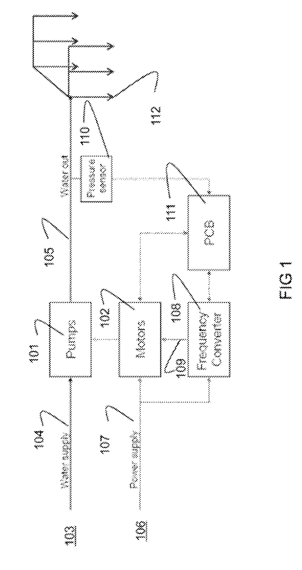
[0025]A fire protection system, such as a water mist extinguishing system, more particularly a high-pressure water mist extinguishing system, comprises spray heads that comprise spray nozzles and are disposed in a fire-protected space, a pump unit, and also piping with actuators for conducting extinguishing fluid from the pump unit to the spray nozzles. The pump unit comprises a number of pump drives, each of which comprises a high-pressure pump and an AC electric motor rotating it.

[0026]The system functions as presented in the above description of prior art, i.e. if the temperature rises in the fire-protected space above the thermal value of the spraying nozzles, the thermal ampoule in the nozzle breaks and lets water flow as mist into the protected space. In this invention the high-pressure pump functioning as the standby pump, which is controlled with a frequency converter, tries to keep 25 bar pressure in the piping and starts to pump more water into the piping, which brings abo...


PUM


Abstract

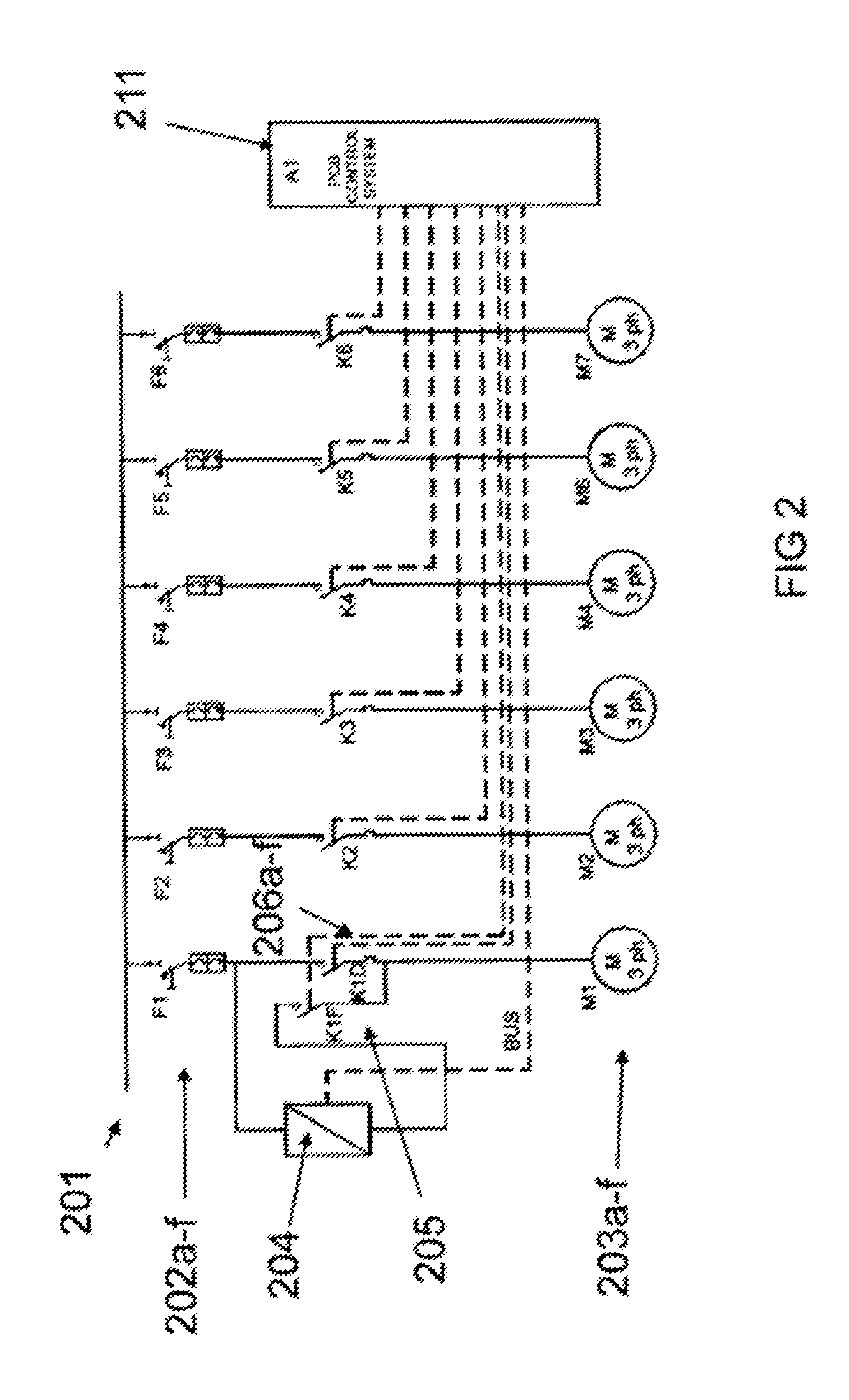
A fire protection system is provided including spray nozzles a pump unit, a control system with pressure-measuring mechanism, and piping for conducting extinguishing medium from the pump unit to the spray nozzles. The pump unit includes pump drives, each of which comprises a pump and an AC electric motor. The AC motor can be connected to an AC electricity network via a contactor device, in which pump unit the AC electric motors are controlled on the basis of the pressure measured in the piping. One of the electric motors is controlled by means of a frequency converter such that the motor steplessly adjusts pressure and the others are started up into the network as steplessly adjusting motors.

Description

CROSS-REFERENCE TO RELATED APPLICATIONS[0001]This application is a U.S. National Stage application of PCT / FI2011 / 050923 filed Oct. 21, 2011, which claims priority to FI Application No. 20106174 filed Nov. 8, 2010, the entire disclosures of which are hereby incorporated herein by reference in their entireties.FIELD OF THE INVENTION[0002]The present invention relates to fire protection systems, and more particularly to high-pressure water mist extinguishing systems.[0003]More particularly, the object of the present invention is a control method and control apparatus of the electric motors of a pump unit of a fire protection system, such as a water mist extinguishing system, more particularly a high-pressure water mist extinguishing system.PRIOR ART[0004]Nowadays pump units consisting of AC electric motors, power transmissions, high-pressure water pumps and unloading valves, with the purpose of these being to regulate the pressure in an activation situation, typically to a pressure of ...

Claims


Application Information

Patent Timeline
Patent Type & Authority Patents(United States)
IPC IPC(8): A62C35/68A62C99/00F04D15/02F04D15/00F04B49/06F04B17/03
CPCA62C35/68A62C99/009F04B17/03F04B49/06F04D15/0066F04D15/029F04D15/0209F04B2203/0202F04B2203/0204F04B2205/05A62C35/64A62C37/00A62C99/0072F04D15/00
Inventor AHO, MARKKUKETTUNEN, VESAPENNANEN, PASI
Owner MARIOFF CORP OY
Learn More