
Flexible lighting device having unobtrusive conductive layers

a flexible lighting and conductive layer technology, applied in the direction of semiconductor devices, printed circuits, electrical equipment, etc., can solve the problems of limiting the amount of light the lighting device can produce, limiting their usefulness in space-sensitive situations, and limiting their use, so as to reduce the light transmittance

Active Publication Date: 2016-03-29
GROTE IND
View PDF47 Cites 5 Cited by
  • Summary
  • Abstract
  • Description
  • Claims
  • Application Information

AI Technical Summary

Benefits of technology

[0075]The instant disclosure is provided to further explain in an enabling fashion the best modes of performing one or more embodiments of the present invention. The disclosure is further offered to enhance an understanding and appreciation for the inventive principles and advantages thereof, rather than to limit in any manner the invention. The invention is defined solely by the appended claims including any amendments made during the pendency of this application and all equivalents of those claims as issued.

Problems solved by technology

However, because these designs can be complex, the resulting device can be relatively thick, limiting their usefulness in space-sensitive situations.
Furthermore, the desire to keep devices as thin as possible limits the size of the LEDs that can be used in a lighting device, thereby limiting the amount of light the lighting device can produce.
In addition, many LED devices are rigid devices, which limit their use in many situations by fixing their size and shape.
However, the requirement to have conductive lines to control the operation of the LEDs has not allowed for such a design.

Method used


Image

  • Flexible lighting device having unobtrusive conductive layers
  • Flexible lighting device having unobtrusive conductive layers
  • Flexible lighting device having unobtrusive conductive layers

Examples


Embodiment Construction

[0075]The instant disclosure is provided to further explain in an enabling fashion the best modes of performing one or more embodiments of the present invention. The disclosure is further offered to enhance an understanding and appreciation for the inventive principles and advantages thereof, rather than to limit in any manner the invention. The invention is defined solely by the appended claims including any amendments made during the pendency of this application and all equivalents of those claims as issued.

[0076]It is further understood that the use of relational terms such as first and second, and the like, if any, are used solely to distinguish one from another entity, item, or action without necessarily requiring or implying any actual such relationship or order between such entities, items or actions. It is noted that some embodiments may include a plurality of processes or steps, which can be performed in any order, unless expressly and necessarily limited to a particular or...


PUM


Abstract

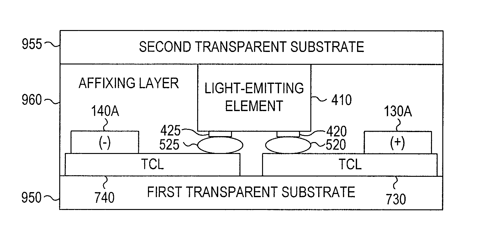
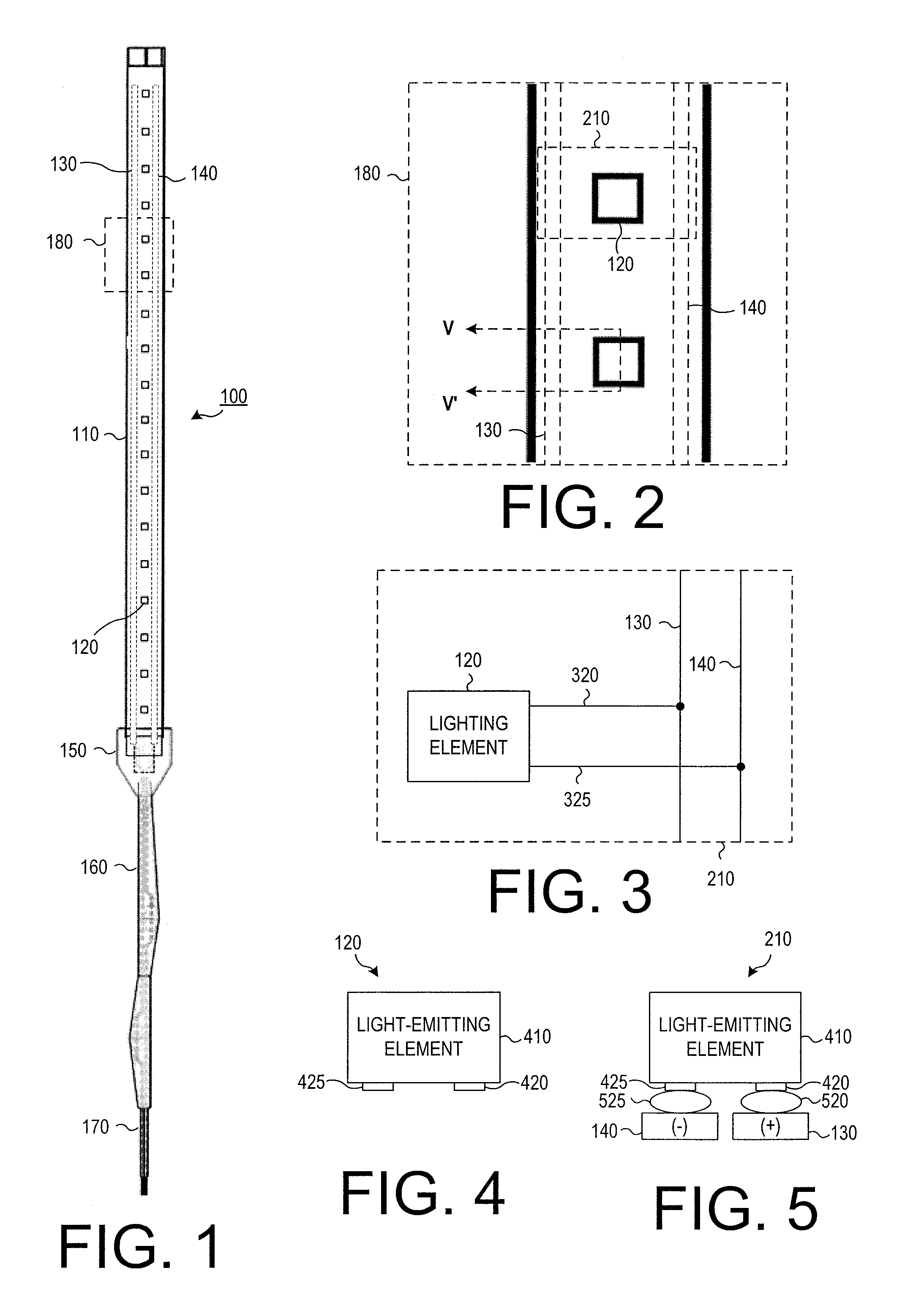
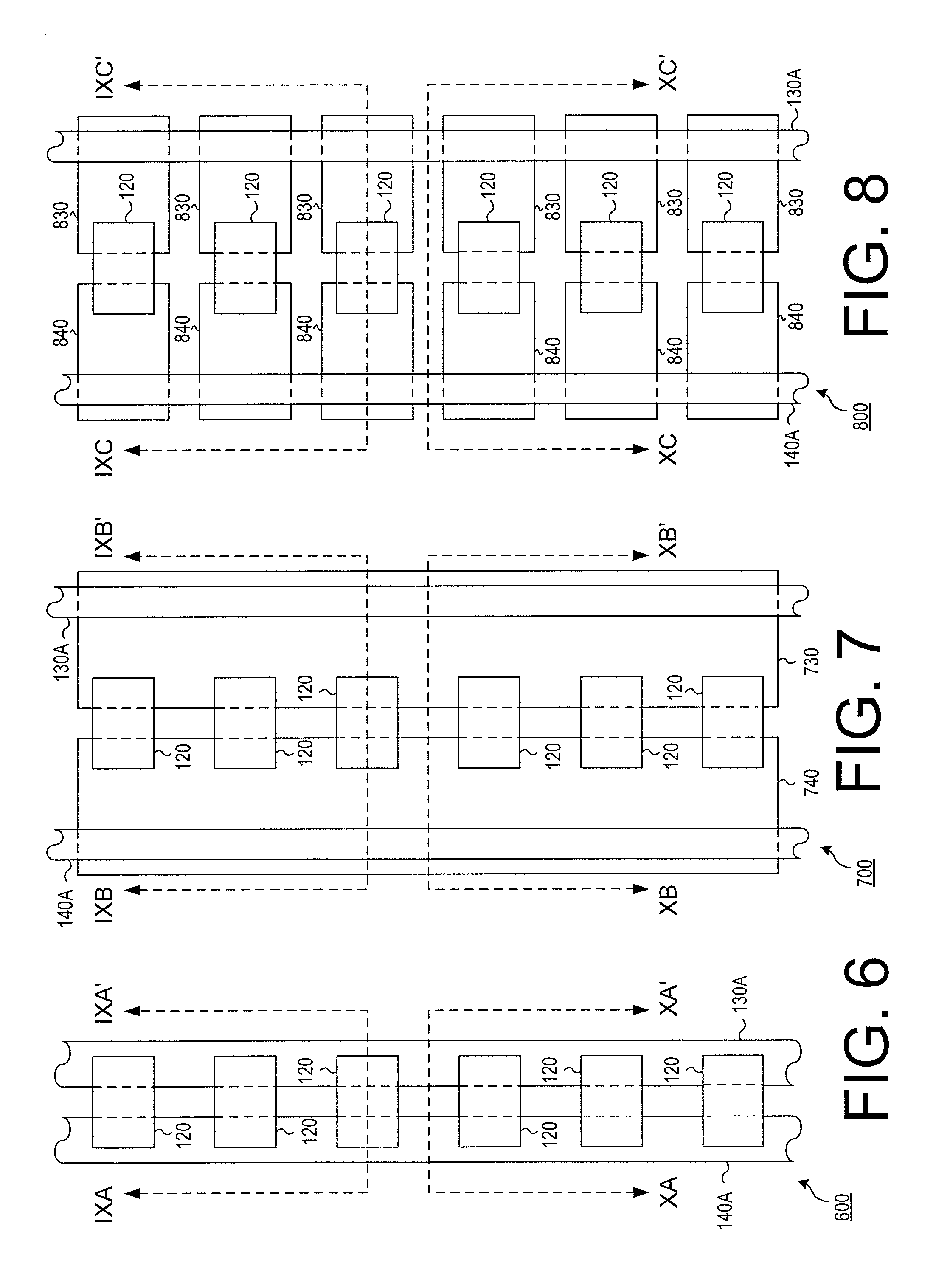
A flexible lighting element is provided, comprising: a first substrate; first and second conductive elements over the first substrate; a light-emitting element having first and second contacts that are both on a first surface of the light-emitting element, the first and second contacts being electrically connected to the first and second conductive elements, respectively, and the light-emitting element emitting light from a second surface opposite the first surface; a transparent layer located adjacent to the second surface; and a transparent affixing layer located between the first substrate and the transparent layer, wherein the transparent layer and the transparent affixing layer are both sufficiently transparent to visible light that they will not decrease light transmittance below 70%, and the first and second conductive layers are at least partially transparent to visible light, or are 300 μm or smaller in width, or are concealed by a design feature from a viewing direction.

Description

FIELD OF THE INVENTION[0001]The present invention relates generally to a thin, flexible device that contains a number of controllable lighting elements on it. More particularly, the present invention relates to a thin, flexible device containing a number of light-emitting diodes that can be controlled to light up, such that only the light-emitting diodes can be easily seen.BACKGROUND OF THE INVENTION[0002]Light-emitting diodes (LEDs) can be used to provide low-cost, low-power lighting in a variety of situations. However, because these designs can be complex, the resulting device can be relatively thick, limiting their usefulness in space-sensitive situations.[0003]Furthermore, the desire to keep devices as thin as possible limits the size of the LEDs that can be used in a lighting device, thereby limiting the amount of light the lighting device can produce.[0004]In addition, many LED devices are rigid devices, which limit their use in many situations by fixing their size and shape.[...

Claims


Application Information

Patent Timeline
Patent Type & Authority Patents(United States)
IPC IPC(8): H01L33/62H01L25/075
CPCH01L25/0753H01L33/62H01L2224/16H01L2933/0066H05K1/028
Inventor CORWIN, WILLIAM, L.GRAMLICH, JR., DONALD, LEEJONES, SCOTT, J.MARX, MARTIN, J.PEREZ-BOLIVAR, CESARRICHARDSON, II, GEORGE, M.ROBERTS, JAMES, E.
Owner GROTE IND
Learn More