Process control system
a technology of process control and control system, applied in the direction of program control, electric programme control, instruments, etc., can solve the problems of affecting the operation of the controller, the life of the process control system is also limited, and the cost of replacing the process control system is not only the cost of replacing the various devices
- Summary
- Abstract
- Description
- Claims
- Application Information
AI Technical Summary
Benefits of technology
Problems solved by technology
Method used
Image
Examples
first preferred embodiment
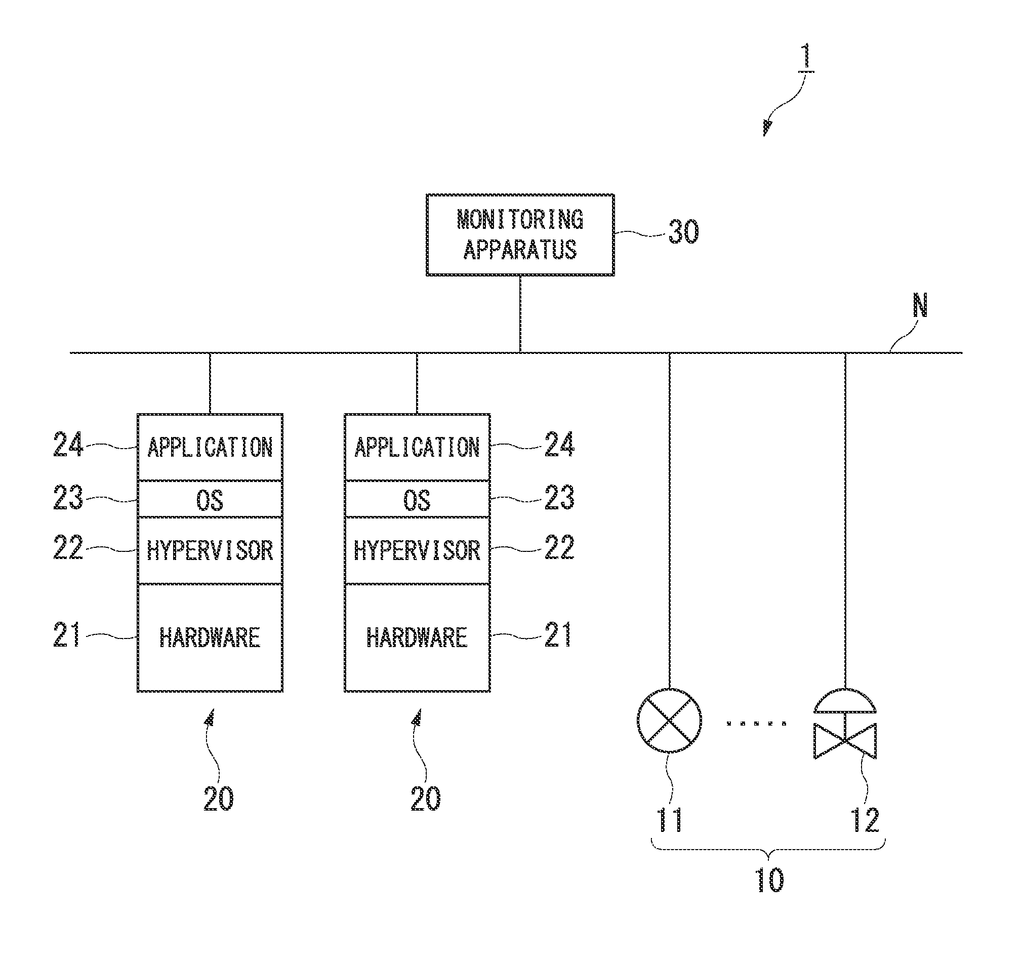
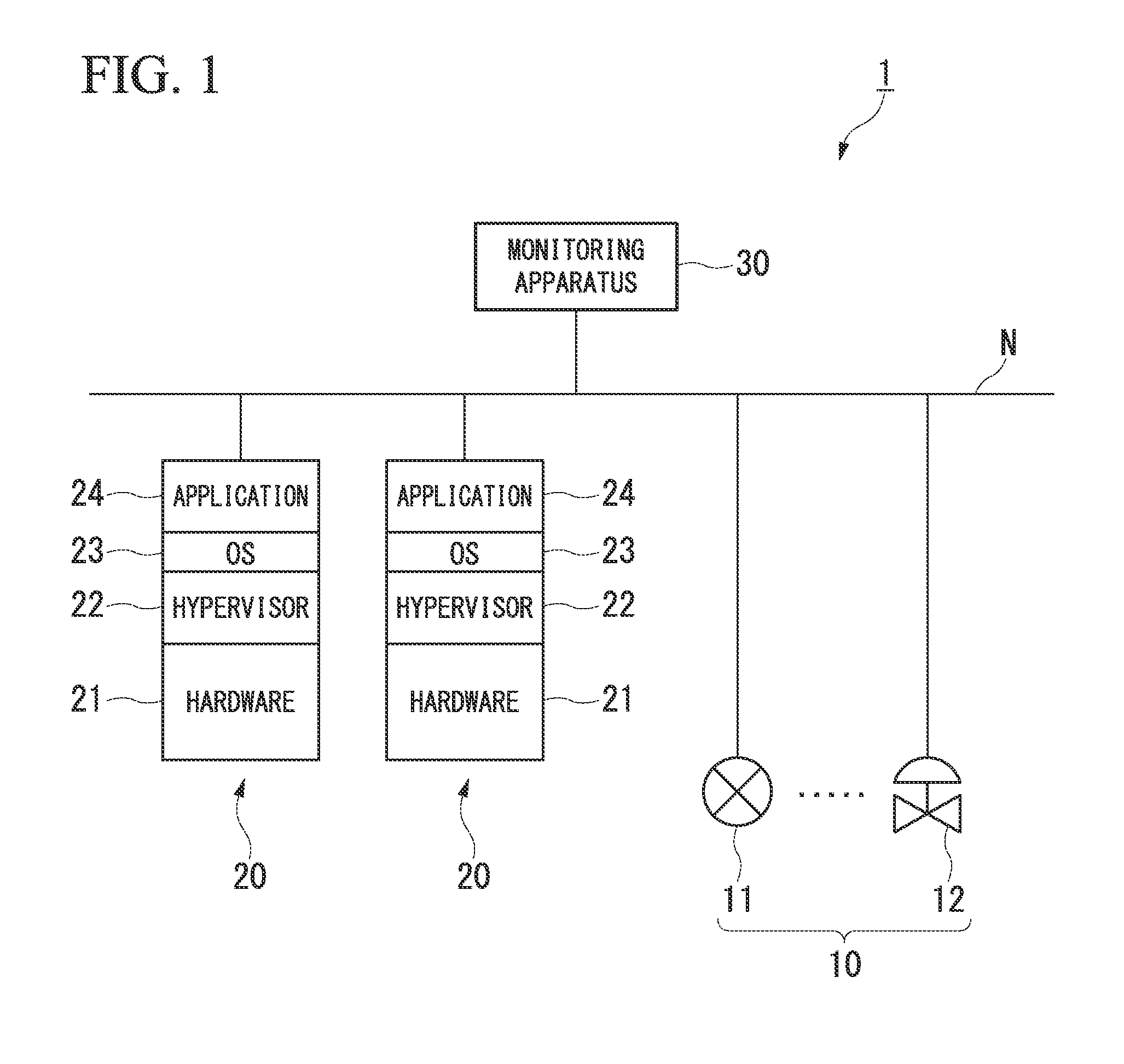
[0035]FIG. 1 is a block diagram illustrating the constitution of the main parts of a process control system in accordance with the first preferred embodiment of the present invention. As shown in FIG. 1, a process control system 1 of the first preferred embodiment has field devices 10, controllers 20, and a monitoring apparatus 30 and, by the controllers 20 controlling the field devices 10 under monitoring by monitoring apparatus 30, the industrial processes implemented in the plant (not shown) are controlled.
[0036]The field devices 10 are, for example, sensor devices such as flow gauges and temperature sensors, valve devices such as flow amount control valves and open / close valves, actuator devices such as fans, and motors, and other devices installed on-site in a plant. In FIG. 1, as an aid to understanding, of the field devices 10 installed in the plant, a sensor device 11 that measures the flow amount of a fluid and a valve device 12 that controls the flow amount of a fluid are ...
second preferred embodiment
[0050]FIG. 3 is a block diagram illustrating the constitution of the main parts of a process control system in accordance with the second preferred embodiment of the present invention. The process control system 2 of the second preferred embodiment imparts redundancy to the constitution of the process control system 1 shown in FIG. 1 for the purpose of increasing the reliability. Specifically, in place of the field devices 10 shown in FIG. 1, the process control system 2 has the field devices 40 and redundant I / O nodes 50 (input / output nodes and, in place of the network N shown in FIG. 1, has redundant networks N1 and N2, and further, in place of the controllers 20 shown in FIG. 1, has the redundant controllers 20a and 20b. The redundant I / O nodes may be referred to as input / output nodes.
[0051]Although the field devices 40, similar to the field devices 10 shown in FIG. 1, are devices that are installed on-site in a plant, they differ from the field devices 10 in FIG. 1 in that they ...
third preferred embodiment
[0067]FIG. 6 is a block diagram illustrating the constitution of the main parts of a process control system in accordance with the third preferred embodiment of the present invention. The process control system 3 of the third preferred embodiment, in addition to providing redundancy between different controllers within which a plurality of applications 24 that control the field devices 10 are caused to run, a spare controller is additionally provided for the controllers.
[0068]Specifically, the process control system 3, as shown in FIG. 6, has controllers 60a to60c, within which a plurality of applications 24 run, and a spare controller 70, which are connected to the networks N1 and N2. For the purpose of simplification, the monitoring apparatus 30, the field devices 40, and the redundant I / O nodes 50 and the like shown in FIG. 3 have been omitted in FIG. 6.
[0069]As shown in FIG. 6, two applications 24 that run without mutual interference in the operating system 23 are implemented wi...
PUM
 Abstract
Description
Claims
Application Information
 - R&D
- Intellectual Property
- Life Sciences
- Materials
- Tech Scout
- Unparalleled Data Quality
- Higher Quality Content
- 60% Fewer Hallucinations
Browse by: Latest US Patents, China's latest patents, Technical Efficacy Thesaurus, Application Domain, Technology Topic, Popular Technical Reports.
© 2025 PatSnap. All rights reserved.Legal|Privacy policy|Modern Slavery Act Transparency Statement|Sitemap|About US| Contact US: help@patsnap.com


