Vibration condition monitoring system and methods

a condition monitoring and vibration technology, applied in the direction of instruments, measurement devices, scientific instruments, etc., can solve the problems of complex monitoring and diagnostic of the mechanical condition of machine components, affecting the overall equipment performance and effectiveness, and requiring extensive machinery

Active Publication Date: 2016-01-26
BAKER HUGHES INC
View PDF21 Cites 24 Cited by
  • Summary
  • Abstract
  • Description
  • Claims
  • Application Information

AI Technical Summary

Problems solved by technology

During normal operations, the equipment may encounter undesired conditions (e.g., misalignment, looseness, imbalance, etc.) that may potentially affect the overall equipment performance and effectiveness.
Oftentimes, monitoring and diagnosing the mechanical condition of machine components may be complicated due to the complex nature of the machine components within the system.
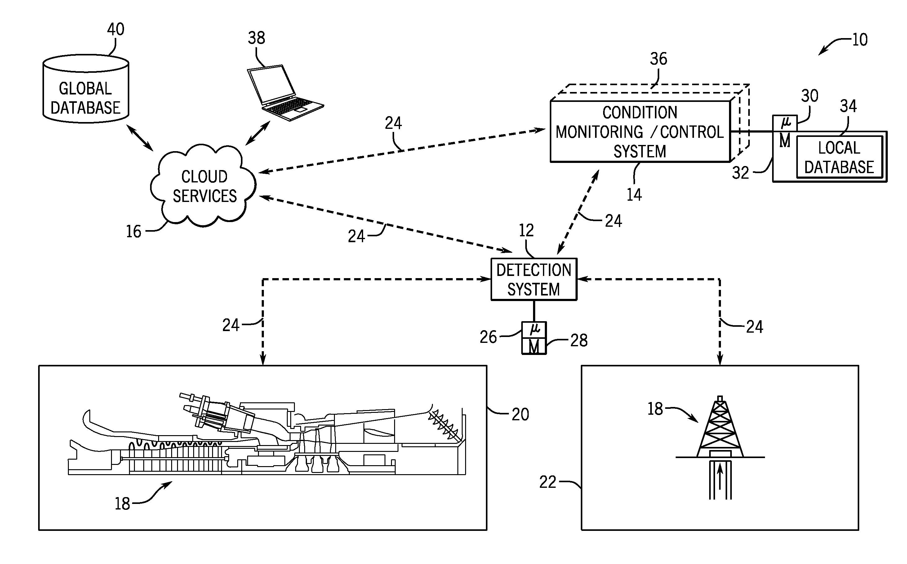
For example, power generation plants and oil and gas operations each involve a plurality of interrelated systems, with each system including complex and extensive machinery.
Monitoring the condition of each machine component within the extensive system may involve a large amount of man power and / or time.
Further, diagnosing a specific machine component failure from within a system of interrelated machine components may involve extensive knowledge, skill, or resources not readily available.
However, it may be unwieldy and time consuming to analyze each parameter from the plurality of sensors in order to diagnose a machine component failure.
Further, it may be cost-prohibitive to perform such monitoring.
However, determining a machine component failure diagnosis from vibration signals often involves vibration specialists and / or specialized procedures and / or tasks.
A vibration specialist visually and subjectively analyzes vibration signals, and an inaccurate and / or delayed analysis could be costly and / or time consuming.
In addition, a vibration specialist may not always be readily available.

Method used


Image

  • Vibration condition monitoring system and methods
  • Vibration condition monitoring system and methods
  • Vibration condition monitoring system and methods

Examples


Embodiment Construction

[0013]One or more specific embodiments will be described below. In an effort to provide a concise description of these embodiments, not all features of an actual implementation are described in the specification. It should be appreciated that in the development of any such actual implementation, as in any engineering or design project, numerous implementation-specific decisions must be made to achieve the developers' specific goals, such as compliance with system-related and business-related constraints, which may vary from one implementation to another. Moreover, it should be appreciated that such a development effort might be complex and time consuming, but would nevertheless be a routine undertaking of design, fabrication, and manufacture for those of ordinary skill having the benefit of this disclosure.

[0014]When introducing elements of various embodiments of the present invention, the articles “a,”“an,”“the,” and “said” are intended to mean that there are one or more of the ele...


PUM

PropertyMeasurementUnit
running speedaaaaaaaaaa
frequencyaaaaaaaaaa
mechanical conditionaaaaaaaaaa

Abstract

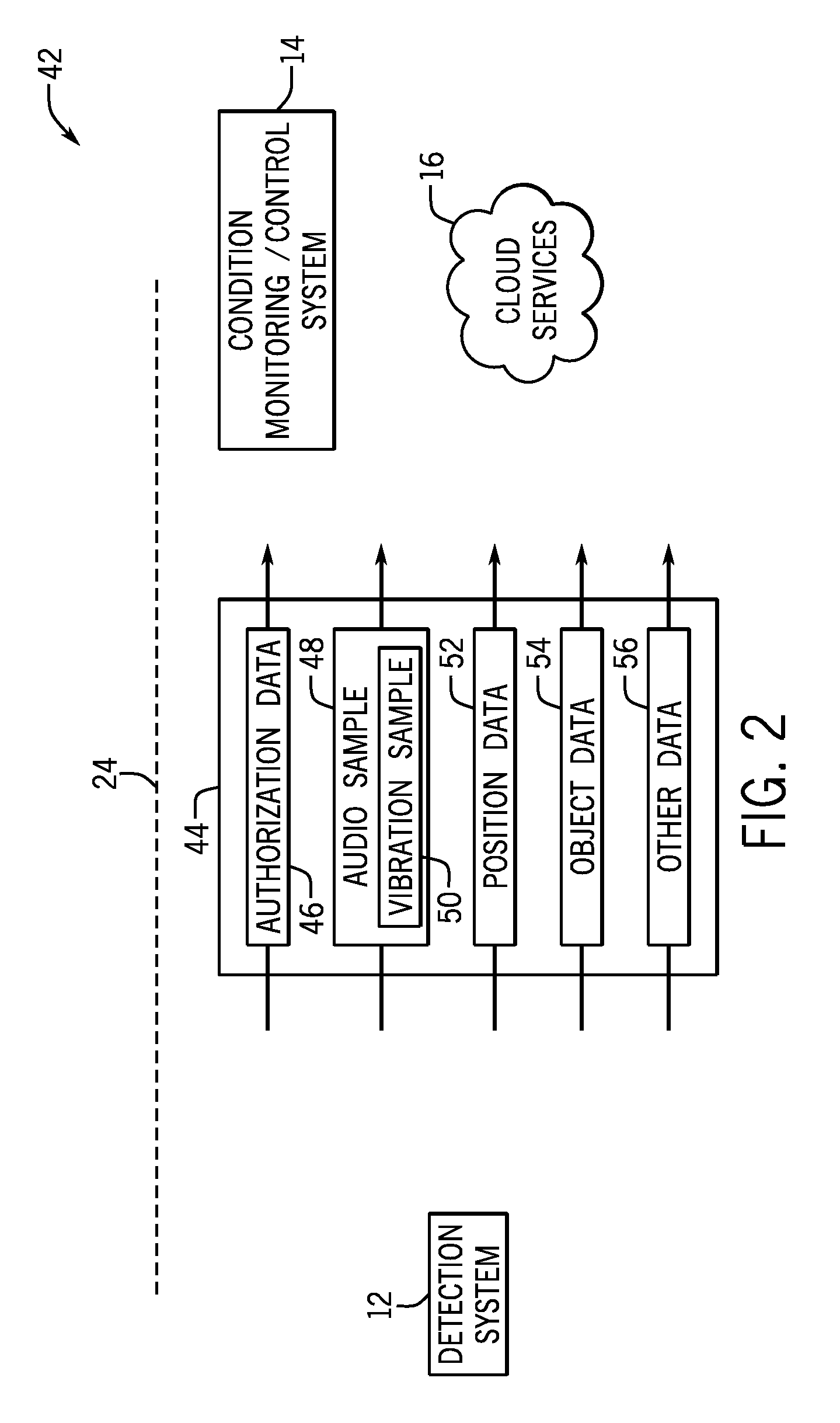
In one embodiment, a diagnostics system is provided. The diagnostics system include a detection system configured to capture acoustic information and contextual information related to a machine component defect. A computing system is coupled to a processor configured to receive the acoustic information and the contextual information from the detection system, select one or more algorithms based at least in part on the contextual information, and retrieve and execute the one or more algorithms to extract one or more characteristic features of the acoustic information. The processor is further configured to generate an acoustic fingerprint based at least in part on the one or more characteristic features of the acoustic information, such that the one or more characteristic features correspond to the machine component defect.

Description

BACKGROUND[0001]The subject matter disclosed herein relates to machine maintenance techniques for industrial systems. More specifically, the subject matter disclosed herein relates to monitoring and diagnosing the mechanical condition of industrial systems based at least partially upon acoustic analyses.[0002]Certain equipment and facilities, such as power generation equipment and facilities, oil and gas equipment and facilities, manufacturing equipment and facilities, and the like, include a plurality of interrelated systems and processes. For example, power generation plants may include turbine systems and processes for operating and maintaining the turbine systems. Likewise, oil and gas operations may include carbonaceous fuel retrieval systems and processing equipment interconnected via pipelines. During normal operations, the equipment may encounter undesired conditions (e.g., misalignment, looseness, imbalance, etc.) that may potentially affect the overall equipment performanc...

Claims


Application Information

Patent Timeline
Patent Type & Authority Patents(United States)
IPC IPC(8): H04R29/00G01N29/46G01N29/44G01N29/14
CPCG01N29/14G01N29/4454G01N29/46H04R29/00G01N2291/2693G01N2291/2696
Inventor RANK, BRANDON, JAMES
Owner BAKER HUGHES INC
Why Eureka
Try Eureka