
Link actuating device

a technology of actuating device and moving plate, which is applied in the direction of gearing, program-controlled manipulators, joints, etc., can solve the problems of limited weight capacity of travelling plate, large apparatus size, and large size of the whole mechanism, and achieve high rigidity, high posture adjusting accuracy, and compact size

Active Publication Date: 2016-01-26
NTN CORP
View PDF13 Cites 9 Cited by
  • Summary
  • Abstract
  • Description
  • Claims
  • Application Information

AI Technical Summary

Benefits of technology

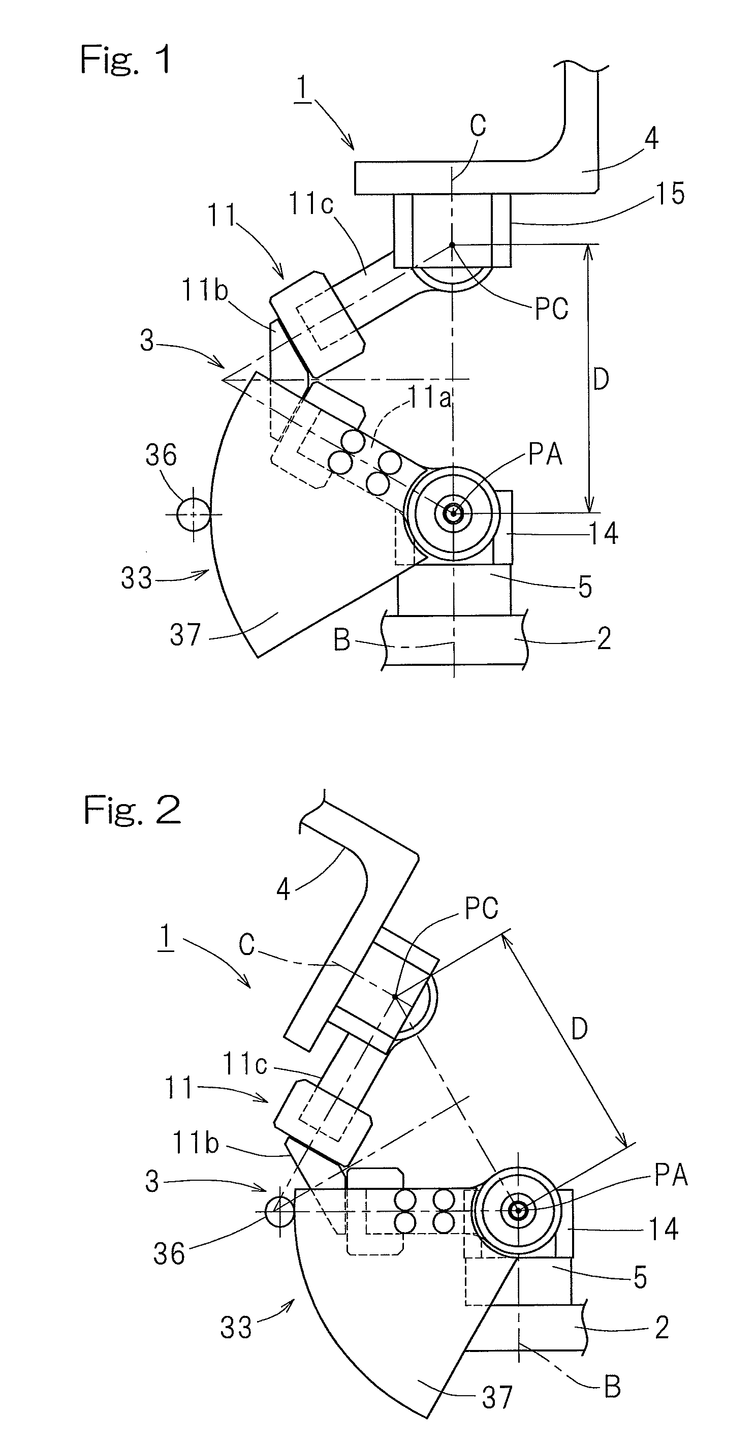
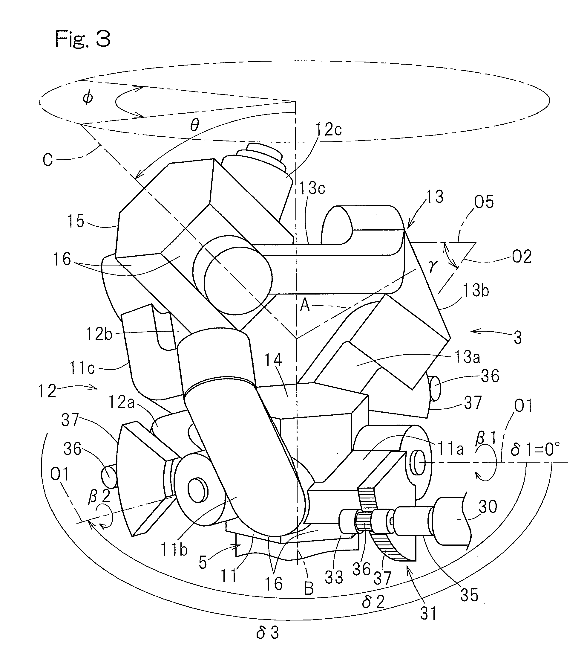
[0008]In view of the foregoing, the present invention has for its object to provide a link actuating device that is compact in size and has a high rigidity, in which the operating range of a movable section is large and a posture adjusting accuracy is high.

Problems solved by technology

Accordingly, a problem has been found that the dimension of the mechanism as a whole increases and the apparatus tends to be bulky in size.
For this reason, there has been a problem that the weight of a tool mounted on the travelling plate, that is, the weight capacity of the travelling plate is limited to a small value.

Method used


Image

  • Link actuating device
  • Link actuating device
  • Link actuating device

Examples


third embodiment

[0073]Also, as is the case with a third preferred embodiment of the present invention as shown in FIG. 8, the actuator 30 may be disposed at a position reverse to the small gear 36. Other than the position of the actuator 30, it is the same as that in the embodiment shown in and described with reference to FIGS. 1 to 6. In the case of the third embodiment, although it may occur that the range of operation will be narrowed as a result of interference of the intermediate link member 11b to 13b with the actuator 30 and / or the motor fixing member 32, the entirety may assume a compact structure.

[0074]FIGS. 9 to 11 illustrate a fourth preferred embodiment of the present invention. As best shown in FIG. 9, the link actuating device 1 according to this fourth embodiment is similar to that shown in and described with reference to FIGS. 1 to 6 in connection with the previously described first embodiment, but differs therefrom in respect that in the fourth embodiment the use of a preloading me...

sixth embodiment

[0084]Even with the link actuating device 1 functions and effects similar to those afforded by the previously described embodiments can be obtained. In addition, the use of the small gear 36 in the form of the work and the large gear 37 in the form of the work wheel is effective to facilitate the manufacture of the small gear 36 and the large gear 37 and a large speed reducing ratio can be obtained.

[0085]In each of the foregoing embodiments, although the use has been made of the reduction gear units 31 and the actuators 30 of all of the three set of the link mechanisms 11 to 13, even when the structure is employed in which the actuator 30 and the reduction gear unit 31 are employed for only two sets of the link mechanism, the posture of the distal end side link hub 15 can be altered relative to the proximal end side link hub 14. It is, however, to be noted that as compared with the case in which they are provided for the three set, there is the possibility that a rattling motion ma...


PUM


Abstract

A distal side link hub is connected with a proximal end side link hub through three sets of link mechanisms for alteration in posture. At least two sets of the link mechanisms include an actuator for arbitrarily changing the posture of the distal end side link hub relative to the proximal end side link hub by rotating a proximal side end link member and a reduction gear unit for reducing the speed of and transmitting the operation amount of the actuator to the proximal side end link member. The reduction gear unit includes a geared speed reducing section having a small gear rotated by the actuator and a large gear provided in the proximal side end link member. The radius of pitch circle of the large gear is chosen to be equal to or greater than the arm length of the proximal side end link member.

Description

CROSS REFERENCE TO THE RELATED APPLICATIONS[0001]This application is a U.S. national stage application of PCT / JP2011 / 073142 filed Sep. 11, 2012, and claims foreign priority benefit of Japanese Application No. 2011-207724 filed Sep. 22, 2011, in the Japanese Intellectual Property Office, the contents of both of which are incorporated herein by reference.BACKGROUND OF THE INVENTION[0002]1. Field of the Invention[0003]The present invention relates to a link actuating device which can be used in a link mechanism such as, for example, a parallel link mechanism or a robot joint for executing, accurately and at high speed, a process work such as, for example, a complicated processing or a goods handling in the three dimensional space.[0004]2. Description of Related Art[0005]One example of the working device equipped with the parallel link mechanism is disclosed in the patent document 1 listed below. The working device disclosed in the patent document 1 is so designed that the position and ...

Claims


Application Information

Patent Timeline
Patent Type & Authority Patents(United States)
IPC IPC(8): B25J17/00F16H19/08B25J9/00B25J17/02B25J9/10F16H37/14B25J18/00F16H21/46
CPCF16H19/08B25J9/0048B25J9/102F16H37/14F16H21/46Y10T74/188Y10T74/18792
Inventor ISOBE, HIROSHIYAMADA, HIROYUKINISHIO, YUKIHIRO
Owner NTN CORP
Learn More