
Interleaved approach to depth-image-based rendering of stereoscopic images

a technology of depth image and stereoscopic image, applied in the field of stereoscopic image processing, can solve the problems of blurry image, unnatural stretching of gaps, less depth information, etc., and achieve the effect of more realistic appearan

Active Publication Date: 2016-01-19
NVIDIA CORP
View PDF6 Cites 118 Cited by
  • Summary
  • Abstract
  • Description
  • Claims
  • Application Information

AI Technical Summary

Benefits of technology

This approach results in stereoscopic images with a more realistic appearance by using actual pixel data from the same eye for gap filling, improving image quality and reducing artifacts near disoccluded areas.

Problems solved by technology

Additionally, depth information consumes less space and compresses more efficiently than image information.
Depth frame smoothing reduces high frequency noise, which is the primary cause of holes in the generated image.
As a result, the gaps are less noticeable, but the generated image may appear blurry or objects in the image that are near the gaps may appear to be unnaturally stretched.
One drawback with these approaches is that the gaps are filled with image data that is not actually seen by the second eye, resulting in a less realistic appearance.

Method used


Image

  • Interleaved approach to depth-image-based rendering of stereoscopic images
  • Interleaved approach to depth-image-based rendering of stereoscopic images
  • Interleaved approach to depth-image-based rendering of stereoscopic images

Examples


Embodiment Construction

[0016]In the following description, numerous specific details are set forth to provide a more thorough understanding of the present invention. However, it will be apparent to one of skill in the art that the present invention may be practiced without one or more of these specific details.

System Overview

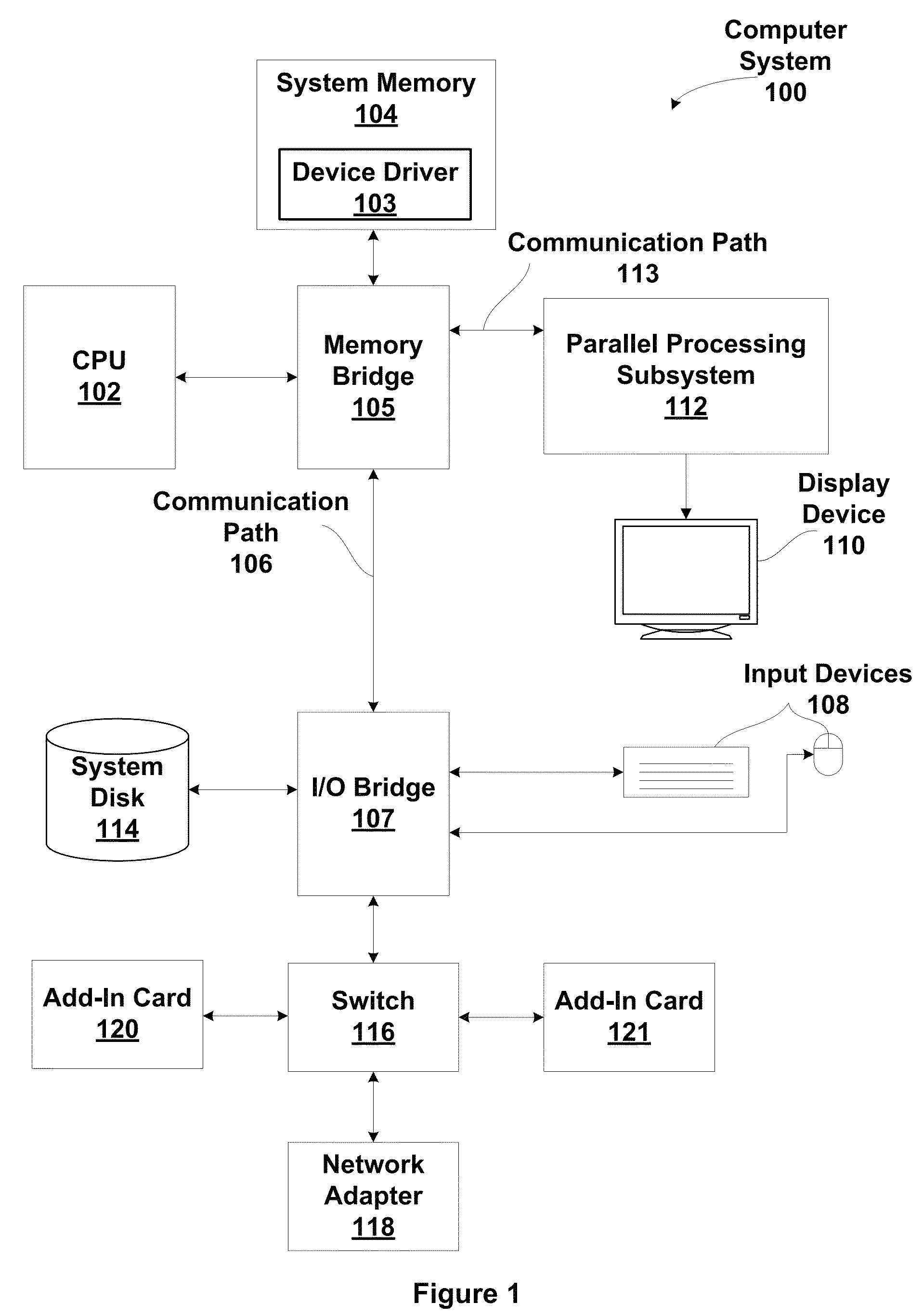
[0017]FIG. 1 is a block diagram illustrating a computer system 100 configured to implement one or more aspects of the present invention. Computer system 100 includes a central processing unit (CPU) 102 and a system memory 104 communicating via an interconnection path that may include a memory bridge 105. Memory bridge 105, which may be, e.g., a Northbridge chip, is connected via a bus or other communication path 106 (e.g., a HyperTransport link) to an I / O (input / output) bridge 107. I / O bridge 107, which may be, e.g., a Southbridge chip, receives user input from one or more user input devices 108 (e.g., keyboard, mouse) and forwards the input to CPU 102 via communication path 106 and m...


PUM


Abstract

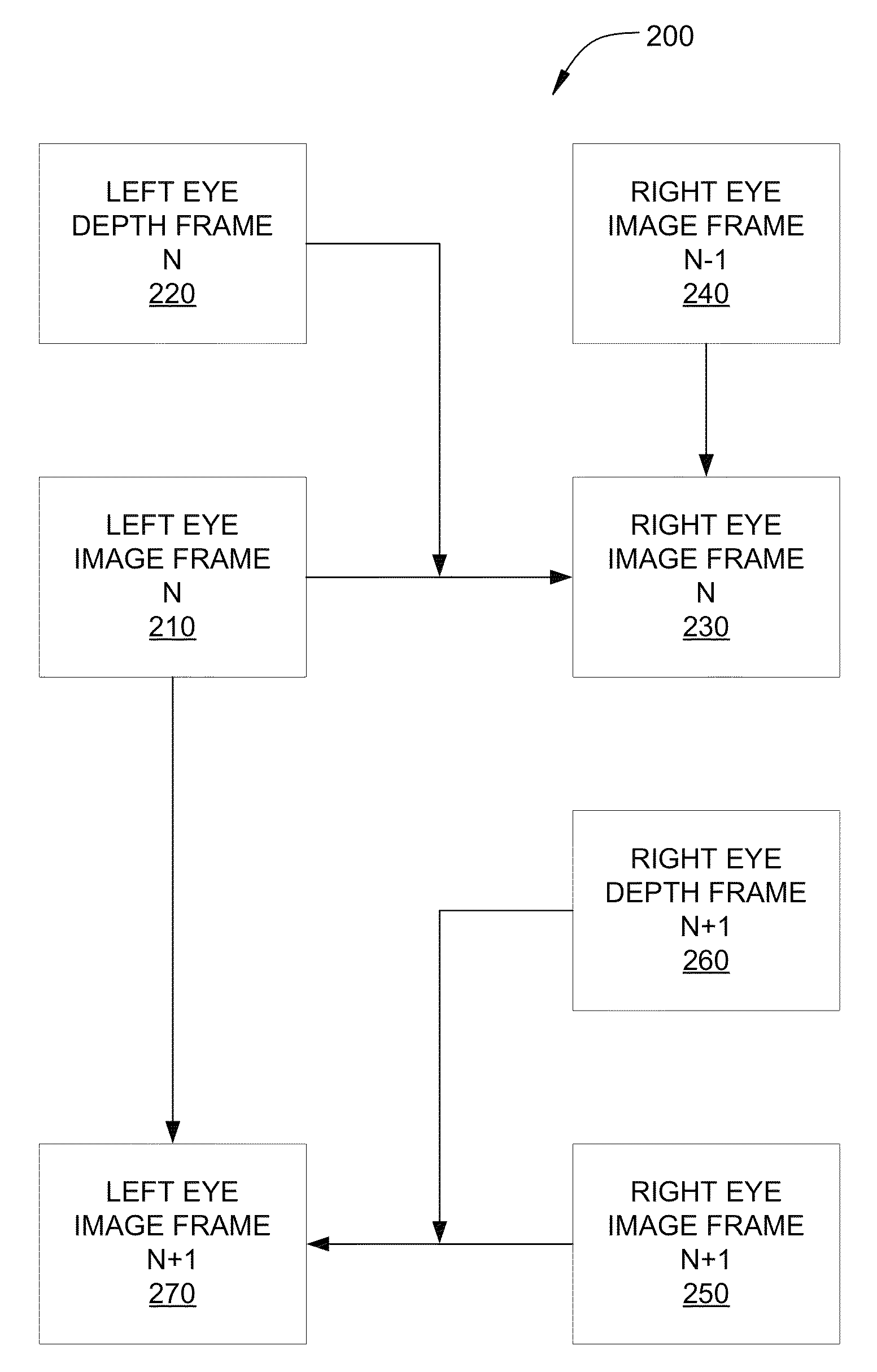
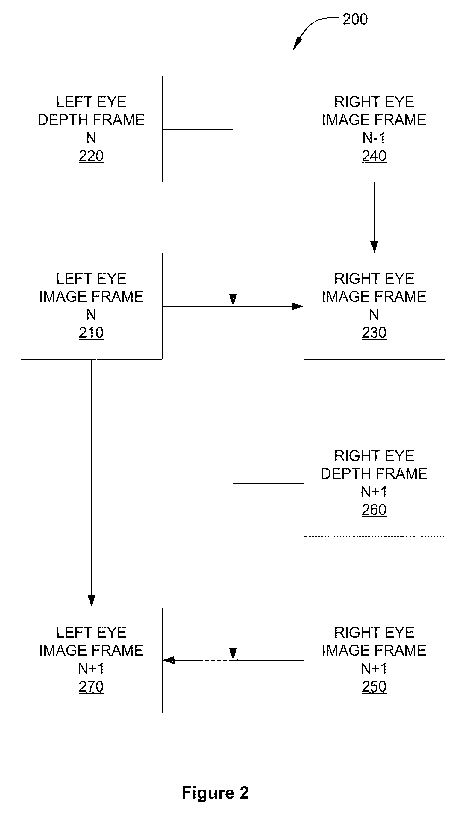
Techniques are disclosed for generating stereoscopic images. The techniques include receiving a first image frame associated with a first eye, and receiving a first depth frame associated with the first eye. The techniques further include reprojecting the first image frame based on the first depth frame to create a second image frame associated with a second eye. The techniques further include identifying a first pixel in the second image frame that remains unwritten as a result of reprojecting the first image frame, and determining a value for the first pixel based on a corresponding pixel in a prior image frame associated with the second eye. One advantage of the disclosed techniques is that DIBR reprojected image frames have a more realistic appearance where gaps are filled using pixels from a prior image for the same eye.

Description

BACKGROUND OF THE INVENTION[0001]1. Field of the Invention[0002]The present invention generally relates to stereoscopic image processing, and, more particularly, to an interleaved approach to depth-image-based rendering of stereoscopic images.[0003]2. Description of the Related Art[0004]Stereoscopic imagery is created by generating separate image frames for the left eye and the right eye, creating a three-dimensional viewing experience. In order to reduce the rendering and transmission time needed to generate two separate image streams, stereoscopic imagery may be accomplished by rendering images and depth information for one eye. Images for the second eye are then generated using a post-rendering process called depth-image-based rendering (DIBR). With DIBR, images are rendered for only one eye, thus reducing rendering time as compared rendering images for both eyes. Additionally, depth information consumes less space and compresses more efficiently than image information. Therefore...

Claims


Application Information

Patent Timeline
Patent Type & Authority Patents(United States)
IPC IPC(8): H04N13/00
CPCH04N13/0011H04N2213/003H04N13/111
Inventor NEILL, PATRICK
Owner NVIDIA CORP
Learn More