
Light-emitting arrangement with adapted wavelength converter

a technology of wavelength converter and light-emitting arrangement, which is applied in the direction of point-like light source, semiconductor device of light source, lighting and heating apparatus, etc., can solve the problems of reducing system efficiency and high cost of optical elements

Inactive Publication Date: 2016-01-19
KONINK PHILIPS ELECTRONICS NV +1
View PDF27 Cites 1 Cited by
  • Summary
  • Abstract
  • Description
  • Claims
  • Application Information

AI Technical Summary

Benefits of technology

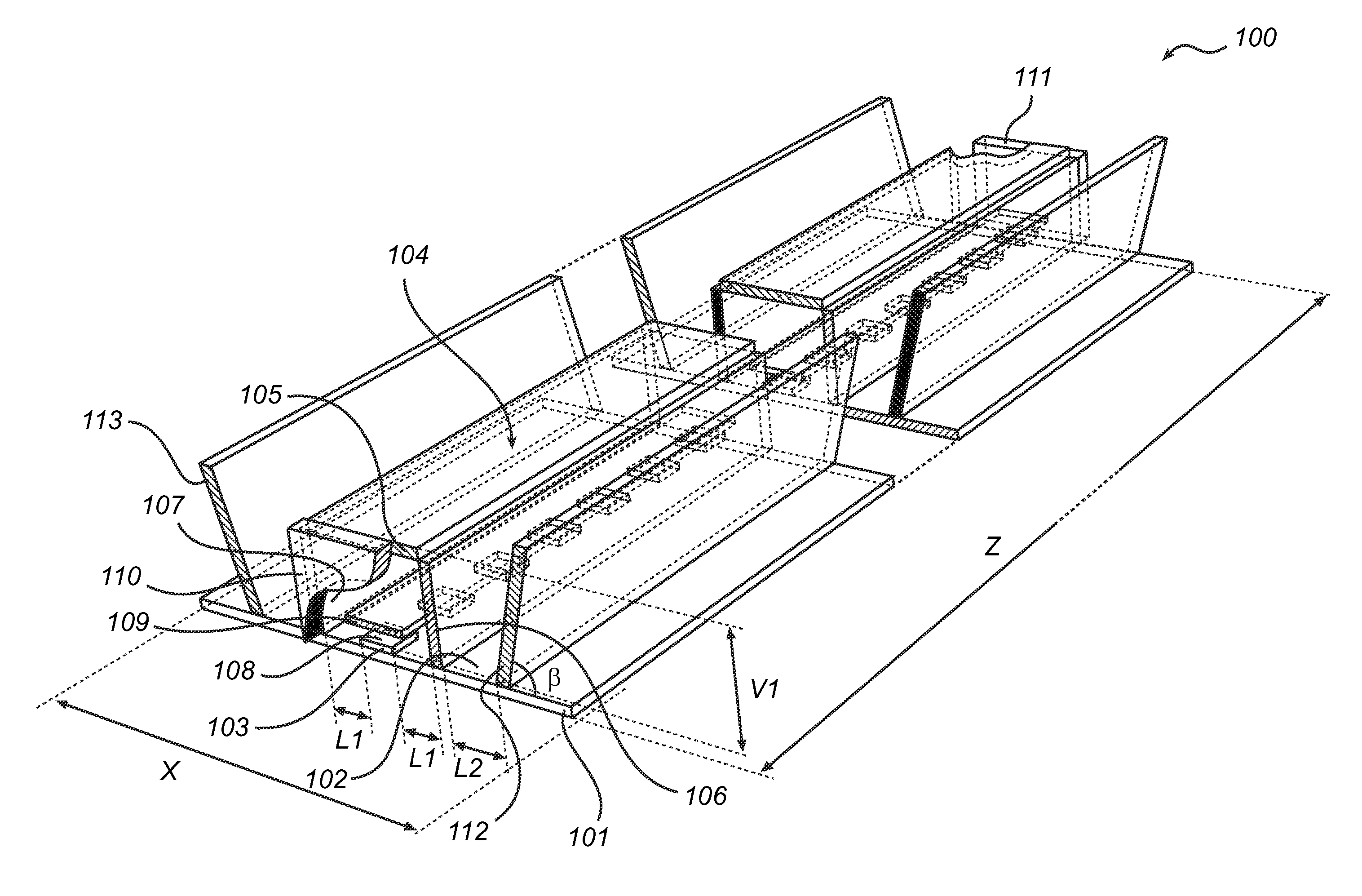
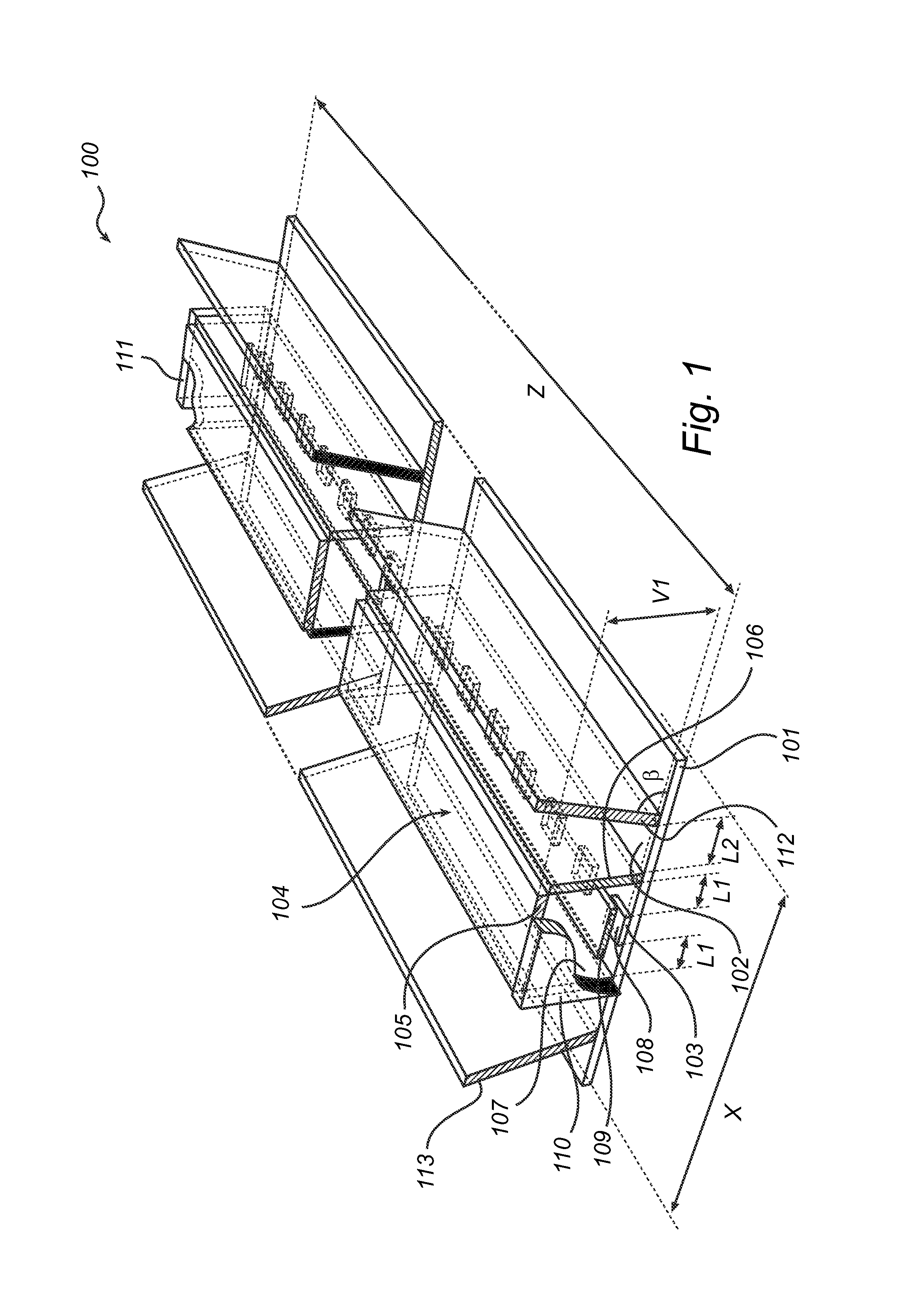
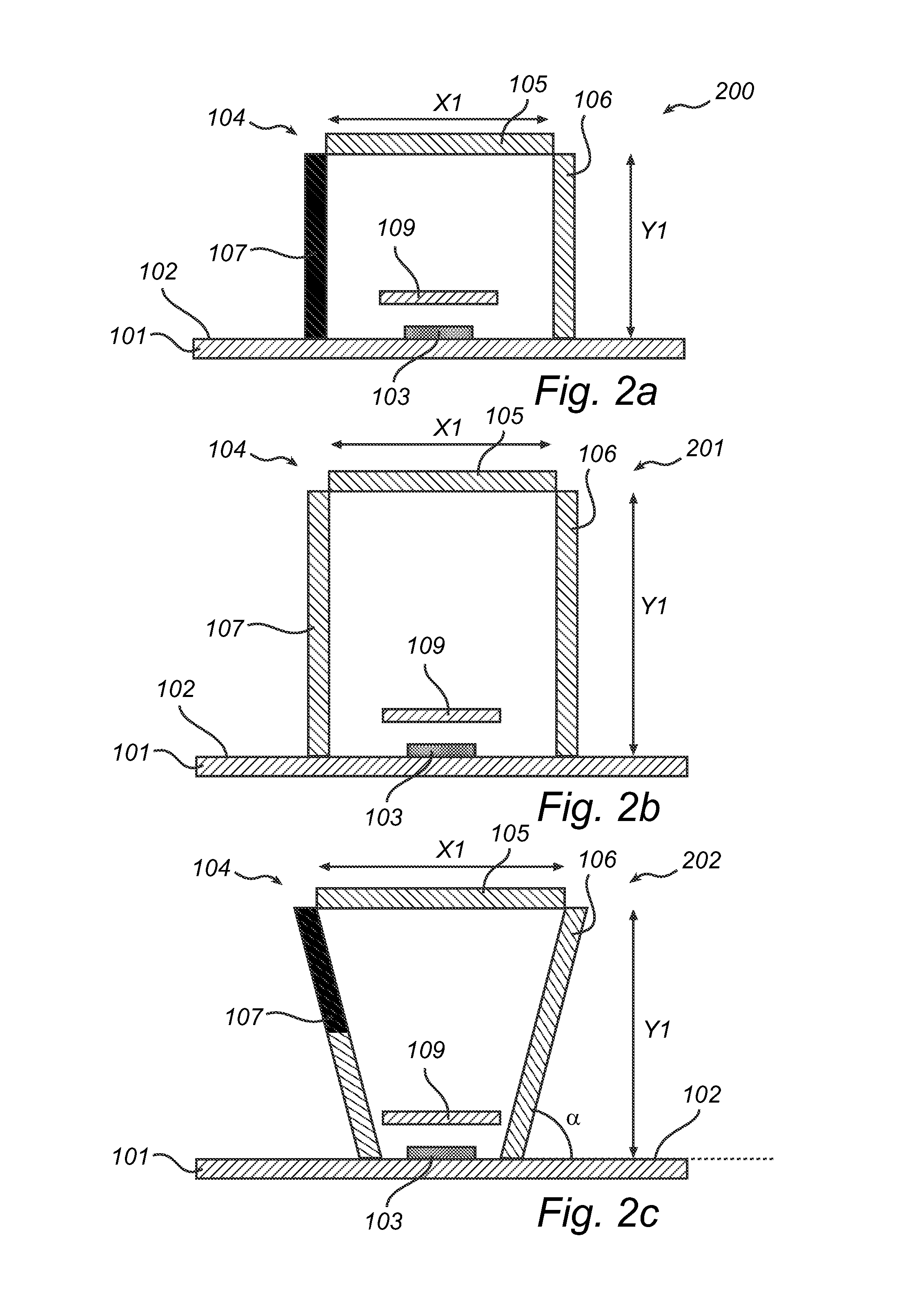
The present invention provides a LED-based light-emitting arrangement with a specific light distribution without the need of expensive optics. The arrangement includes a redirecting member, such as a diffusing optical element, refractive optical element, diffractive optical element, or reflective optical element, to redirect light emitted from the LEDs to achieve a uniform spatial spread of the light over the inner surfaces of the faces of the wavelength converting member, thereby reducing the color angle of the output light. The arrangement also includes a first and second planar specular reflector to reflect light from the wavelength converting member to further control the light distribution.

Problems solved by technology

However, such optical elements are usually expensive and may decrease the system efficiency due to optical losses.

Method used


Image

  • Light-emitting arrangement with adapted wavelength converter
  • Light-emitting arrangement with adapted wavelength converter
  • Light-emitting arrangement with adapted wavelength converter

Examples


examples

[0057]A cross-sectional side view of example embodiment of the light-emitting arrangement 400 of the invention is shown in FIG. 4a, where the wavelength converting member 404, arranged at on a PCB 401 having a reflective coating 402, has a top face 405 with a width X2 of 2.50 cm, and a first and a second side face with a width Y2 of 5.00 cm. Furthermore, the first 406 and the second 407 side faces of the wavelength converting member 404 are arranged on a respective side of the LED 403 (on the PCB). The first 412 and the second 413 specular reflectors are each arranged on a respective side of the wavelength converting member 404. Each of the first and the second specular reflectors 412, 413 has a width Y3 of 35.00 cm and is oriented at angle β of 81° with respect to the reflective surface 402 of the PCB 401. The wavelength converting member 404 and the first 412 and the second 413 specular reflectors on the PCB 401 are surrounded by a dome shaped waterproof cover 420 with a width X4 ...


PUM


Abstract

A light-emitting arrangement (100) comprising a reflective member (101) having a reflective surface (102) on which at least one LED is arranged is disclosed. A wavelength converting member (104) comprising a first wavelength converting material, adapted to convert light of a first wavelength into light of a second wavelength, is arranged on the reflective member. The converting member has a top face (105) oriented parallel to the reflective surface, and has a first side face (106) and a second side face (107) that are each arranged between the top face and the reflective member on a respective side of the LED(s). The top face is arranged at a vertical distance (V1) from a light-emitting surface (108) of the LED(s). By adapting the properties, dimensions and / or orientation of the faces of the wavelength converting member according to the invention, a desirable light distribution from the light-emitting arrangement is achieved.

Description

FIELD OF THE INVENTION[0001]The present invention relates to a LED-based light-emitting arrangement.BACKGROUND OF THE INVENTION[0002]Conventional lighting systems including fluorescent lamps have been used for decades but are expected to be replaced by light-emitting diode (LED)-based luminaries in the future. Typically, such LED-based luminaries include a plurality of LEDs.[0003]White light may be obtained from an LED using a blue LED and a wavelength converting material, also known as phosphor, which absorbs part of the blue light emitted by the LED and reemits light of longer wavelength(s). For reasons of efficacy it is preferable to have the wavelength material arranged at a distance from the LED, in a so-called remote configuration.[0004]In the field of lighting for interior and exterior, there is an increasing need for lighting systems having a specific design and function. The purpose of lighting may be the creation of a general illumination or to focus the light on certain a...

Claims


Application Information

Patent Timeline
Patent Type & Authority Patents(United States)
IPC IPC(8): F21K99/00F21V13/02F21V13/08F21V9/16F21V3/00F21V29/00F21V29/502F21V29/503F21V29/504F21V29/70F21Y103/00
CPCF21V13/08F21K9/56F21V9/16F21V13/02F21Y2101/02F21Y2103/003F21Y2103/10F21Y2115/10F21Y2101/00F21V9/38F21V29/70F21V7/005
Inventor HIKMET, RIFAT ATA MUSTAFABIJLSMA, ALBERTVAN BOMMEL, TIES
Owner KONINK PHILIPS ELECTRONICS NV
Learn More