Method for fabricating a funnel
- Summary
- Abstract
- Description
- Claims
- Application Information
AI Technical Summary
Benefits of technology
Problems solved by technology
Method used
Image
Examples
first embodiment
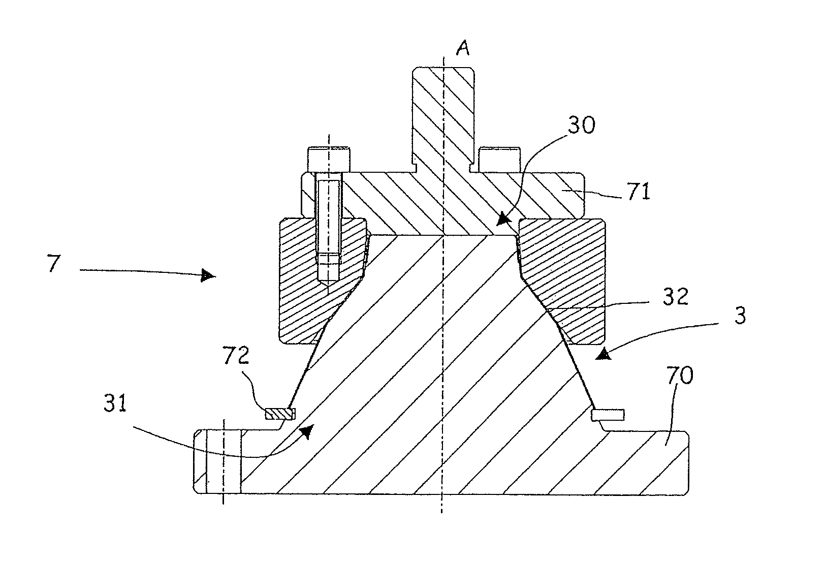
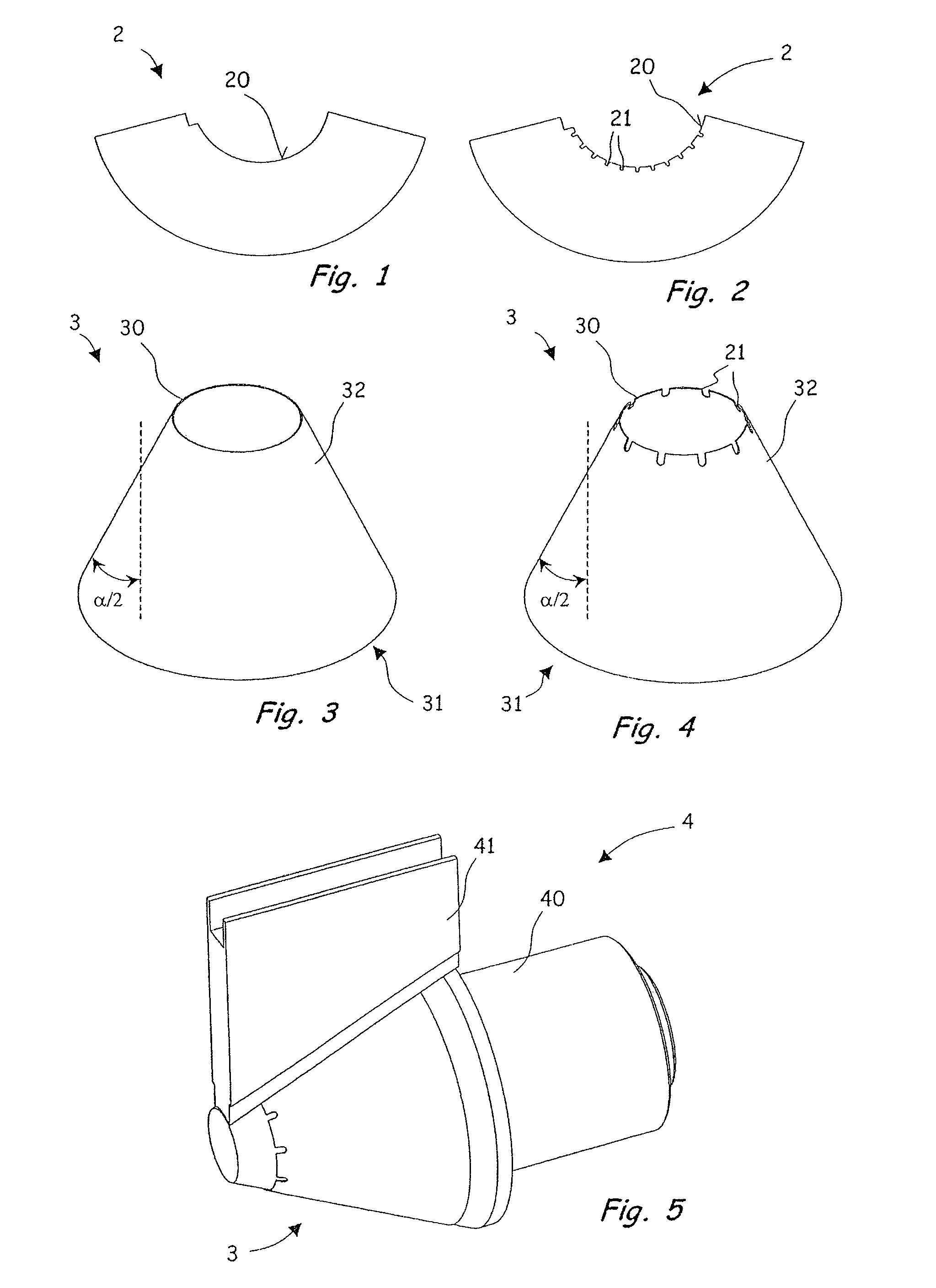
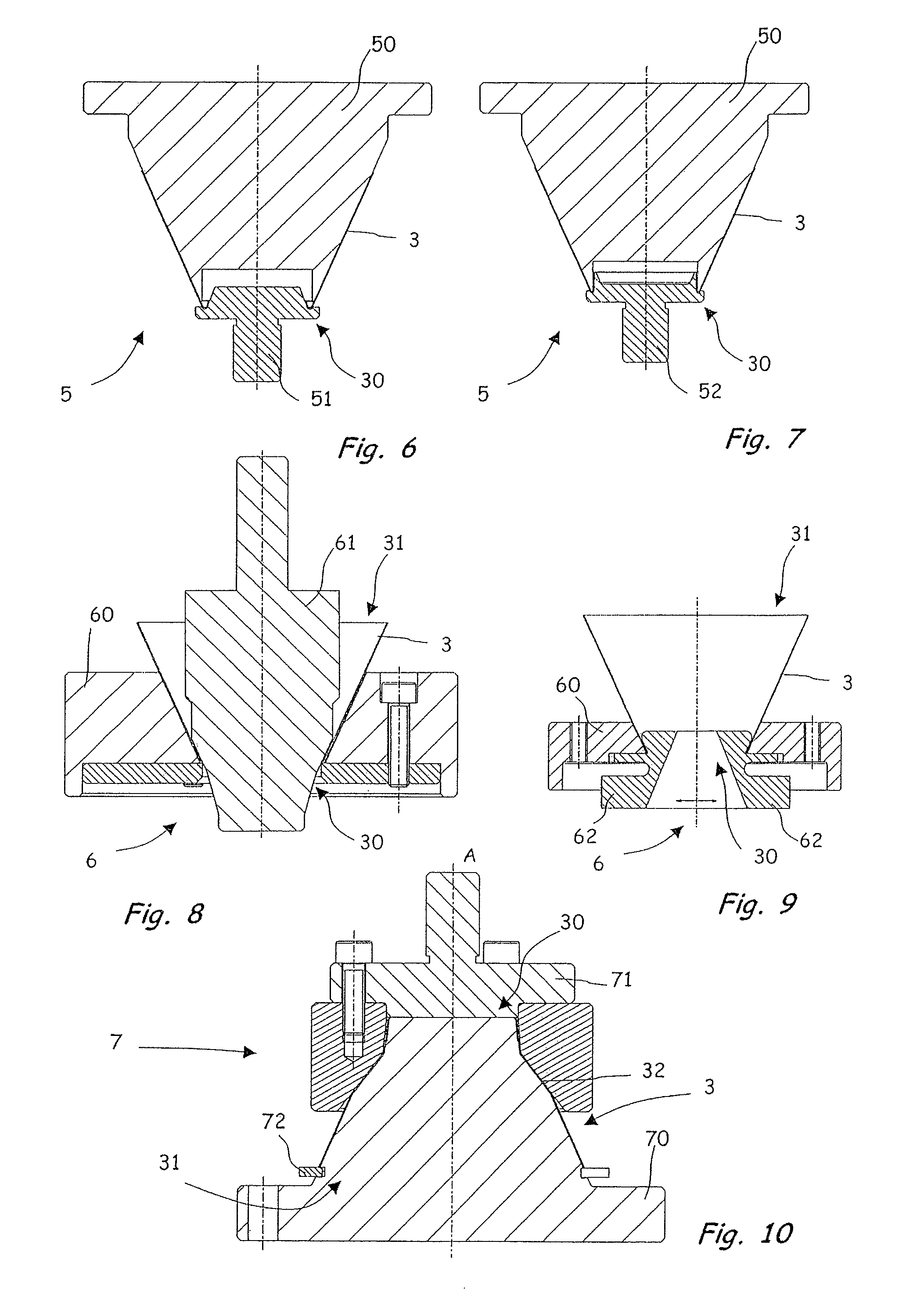
[0065]FIGS. 6 to 12 illustrate the actual procedure for producing a funnel 1 of the invention.
[0066]Firstly, the outlet opening 30 of the sleeve-shaped funnel 3 is stiffened. In the embodiment shown, in order to stiffen the outlet opening 30, the edge 20 of the flat material shown in FIGS. 1 and 2 is turned over and sealed following the shaping procedure for the funnel-shaped sleeve 3.
[0067]FIGS. 6 and 7 diagrammatically illustrate a procedure for creating an edge turnover on the flat material in the region of the outlet opening 30 by means of a tool 5 comprising a die 50 and two plugs 51, 52. In the exemplary embodiment shown, the edge 20 is turned over in the direction of the interior of the funnel-shaped sleeve 3. The procedure for creating an edge turnover on the flat material is carried out in two stages, for which purpose the two plugs 51, 52 are employed in succession. The funnel-shaped sleeve is placed on the stationary die 50 and shaped by means of the plugs 51, 52.
[0068]Sh...
third embodiment
[0087]FIGS. 22 to 26 show a method of the invention for shaping a funnel-shaped sleeve 3 shown in FIG. 4 to a funnel 1, as shown in FIGS. 13 and 14.
[0088]In a work station shown in FIG. 22, the procedure for swaging a portion 32 of the peripheral surface for the purpose of expanding an opening angle of the funnel-shaped sleeve 3 and, at the same time, of stiffening the outlet opening 30 by creating an edge turnover on the flat material in the appropriate region are carried out by a tool 9 comprising a die 90 and a plug 91. Before processing the funnel-shaped sleeve 3 by means of the tool 9, shown in FIG. 22, provision is made, in one embodiment, to pre-shape an edge of the outlet opening 30 by means of a tool 5 comprising the plug 51 shown in FIG. 6. This ensures that the region of the outlet opening 30 has a circular opening, into which the tool component 91 can be inserted. The tool component 91 has an annular groove 910 that cooperates with a complementary projection 900 on the d...
fourth embodiment
[0094]Referring to FIGS. 27 to 35, the method of the invention and also of a funnel produced by the method of the invention, a receptacle containing such a funnel, and also the tools for carrying out the method are described.
[0095]FIG. 27 shows a blank of flat material 100 in the form of a ring segment. The blank of flat material 100 is wrapped around a cone-shaped mandrel, cf. FIG. 5, to form a sleeve having the shape of a truncated cone and is then sealed or glued in the region of an overlap 102 The region of the overlap is provided with a cutout 104 at its top edge of smaller diameter, as shown at the top of FIG. 27, such that in the region of said cutout 104 only a single thickness of material is present after the flat material has been glued to form a sleeve having the shape of a truncated cone. The cutout is rectangular in shape and is disposed at the corner between the turned-over edge of smaller radius and the straight side edge of the annular segment-shaped blank of flat ma...
PUM
| Property | Measurement | Unit |
|---|---|---|
| Angle | aaaaa | aaaaa |
Abstract
Description
Claims
Application Information
 - R&D
- Intellectual Property
- Life Sciences
- Materials
- Tech Scout
- Unparalleled Data Quality
- Higher Quality Content
- 60% Fewer Hallucinations
Browse by: Latest US Patents, China's latest patents, Technical Efficacy Thesaurus, Application Domain, Technology Topic, Popular Technical Reports.
© 2025 PatSnap. All rights reserved.Legal|Privacy policy|Modern Slavery Act Transparency Statement|Sitemap|About US| Contact US: help@patsnap.com


