
Touch sensing device and display device using the same

Active Publication Date: 2015-12-29
LG DISPLAY CO LTD
View PDF7 Cites 56 Cited by
  • Summary
  • Abstract
  • Description
  • Claims
  • Application Information

AI Technical Summary

Benefits of technology

The invention provides a touch sensing device that can adjust the voltage applied to its sensor electrodes and display screen. This device has a feedback voltage transmitter that controls the sensor lines connected to a feedback line. A common voltage compensator receives the feedback voltage and adjusts it to a reference voltage level. This technology allows for more accurate and consistent touch sensing, and can improve the overall performance of the display device.

Problems solved by technology

Although the common voltage should be the same for every pixel, the division of the common electrode into electrodes for the touch sensors makes the common voltage non-uniform on a large-sized screen, causing the deterioration of picture quality.
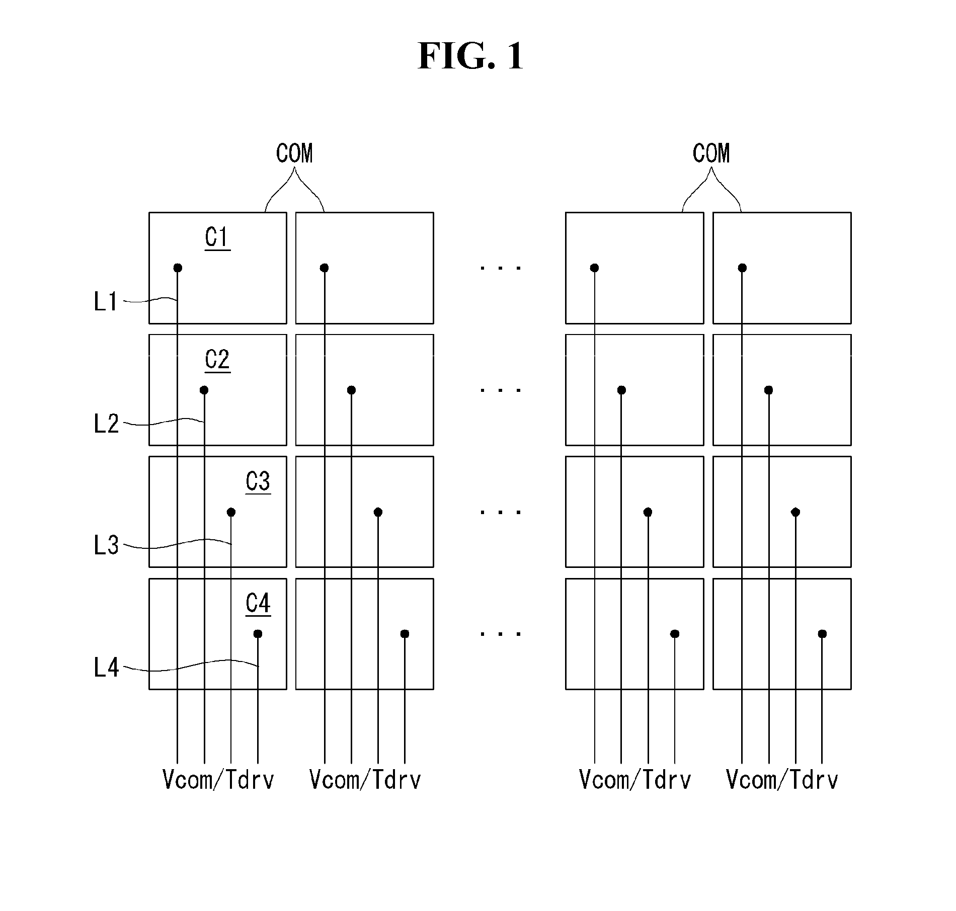
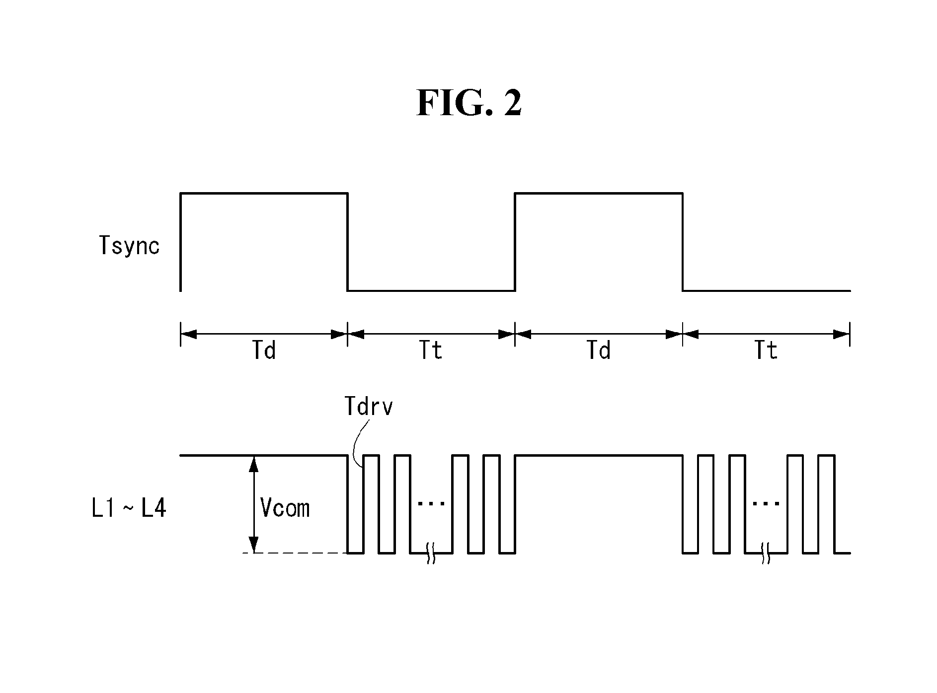
Accordingly, in-cell touch sensor technology might suffer from non-uniformity in the common voltage Vcom applied through the sensor electrodes C1 to C4 during the display driving period Td.
This can result in deterioration of the picture quality of the display device.
Large-screen display devices may have large parasitic capacitance due to coupling between in-cell touch sensors and pixels.
This may increase the size and resolution of a touch screen using the in-cell touch sensors and also increase the parasitic capacitance connected to the in-cell touch sensors, leading to a reduction in touch sensitivity and touch recognition accuracy.
However, the feedback line cannot be connected to each of the sensor electrodes, which may be divided from the common electrode as shown in FIG. 1, so the method of common voltage compensation may not be applicable.

Method used


Image

  • Touch sensing device and display device using the same
  • Touch sensing device and display device using the same
  • Touch sensing device and display device using the same

Examples


Embodiment Construction

[0032]Hereinafter, example embodiments of the present invention will be described in detail with reference to the attached drawings. Throughout the specification, the same or similar reference numerals may indicate substantially the same or similar components. Further, in the following description, well-known functions or constructions related to embodiments of the present invention will not be described in detail if it appears that such description could obscure understanding of the invention.

[0033]The display device of embodiments of the invention may be implemented as a flat panel display such as a liquid crystal display (LCD), a field emission display (FED), a plasma display panel (PDP), an organic light emitting display (OLED), or an electrophoresis display (EPD), for example. In the following description, embodiments of the invention will be described focusing on a liquid crystal display, merely as an example of the flat panel display, but embodiments are not limited thereto. ...


PUM


Abstract

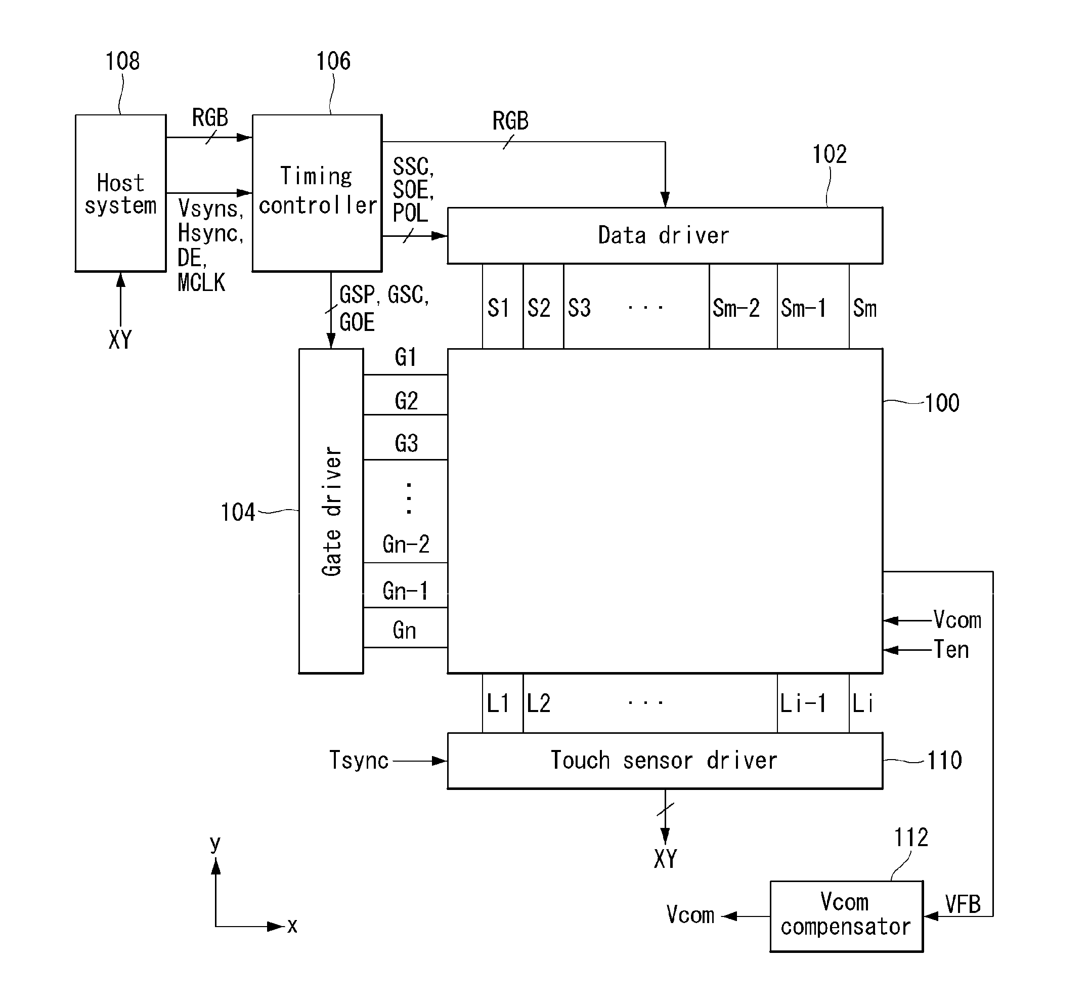
A touch sensing device comprises a common electrode divided into a plurality of sensor electrodes, a plurality of sensor lines respectively connected to the plurality of sensor electrodes, a feedback voltage transmitter, and a common voltage compensator. The feedback voltage transmitter includes a feedback line, a plurality of switching elements configured to selectively connect the sensor lines to the feedback line, and a feedback control line configured to control selection of the switching elements. The common voltage compensator is configured to receive a feedback voltage supplied to the sensor lines through the feedback line while the sensor lines are connected to the feedback line through the plurality of switching elements, and compensate the feedback voltage to a reference voltage level.

Description

[0001]This application claims the benefit of Korean Patent Application No. 10-2014-0119603, filed on Sep. 10, 2014, which is incorporated herein in its entirety by reference for all purposes as if fully asset forth herein.BACKGROUND[0002]1. Field of the Invention[0003]Embodiments of the invention relate to a touch sensing device incorporating touch sensors within a pixel array, and a display device using the same.[0004]2. Discussion of the Related Art[0005]A user interface (UI) is configured so that users are able to communicate with various electronic devices and thus can easily and comfortably control the electronic devices as they desire. Examples of a user interface include a keypad, a keyboard, a mouse, an on-screen display (OSD), and a remote controller having an infrared communication function or a radio frequency (RF) communication function. User interface technologies have continuously expanded to increase users' sensibilities and handling convenience. User interfaces have ...

Claims


Application Information

Patent Timeline
IPC IPC(8): G06F3/041
CPCG06F3/041G06F3/0412G06F3/04166G06F3/0443
Inventor KIM, JAESEUNGSHIN, SEUNGROKLEE, JEONGHOON
Owner LG DISPLAY CO LTD
Learn More