
Uni-directional axial turbine blade assembly

a technology of axial turbine blades and blade assemblies, which is applied in the direction of reaction engines, machines/engines, mechanical equipment, etc., can solve the problems of insufficient air flow and wind pressure of axial fans, inability of axial fans to provide efficient uni-directional rotation, and less efficiency of current uni-directional axial turbine blade assemblies, etc., to achieve uniform rotation, high speed, and convenient configuration

Active Publication Date: 2015-12-22
SHAKIBAPOUR MOHAMMAD ISMAIL ABBASSI
View PDF15 Cites 2 Cited by
  • Summary
  • Abstract
  • Description
  • Claims
  • Application Information

AI Technical Summary

Benefits of technology

The present invention provides an economical, uniformly rotational, simple, uni-directional turbine that can operate at high speeds. The unique design of the uni-directional axial turbine blade assembly provides efficient uni-directional rotation irrespective of changes in flow direction of fluid. Additionally, the design allows for easy configuration and increased power of a rotational shaft when two uni-directional axial turbine blade assemblies are joined together. Overall, the invention provides a more effective tool for generating energy from fluid flow.

Problems solved by technology

Currently used uni-directional axial turbine blade assemblies have less efficiency, because the effective surface area of the blades is limited to tips of the blades, where the linear velocity is greatest.
However, the axial fan can only obtain a sufficiently large air flow and wind pressure when the main vanes are open to air flow from one direction and the sub vanes are open to air flow from the opposite direction.
Therefore, the axial fan cannot provide an efficient uni-directional rotation regardless of the change in flow direction.
The skewed leading edges reduce resistance to the turbine rotation.
However, the reaction turbine has a complicated structural arrangement of blades with additional attachments to provide a uni-directional rotation.
Thus, the complicated construction leads to increased cost of manufacturing and design complexity.

Method used


Image

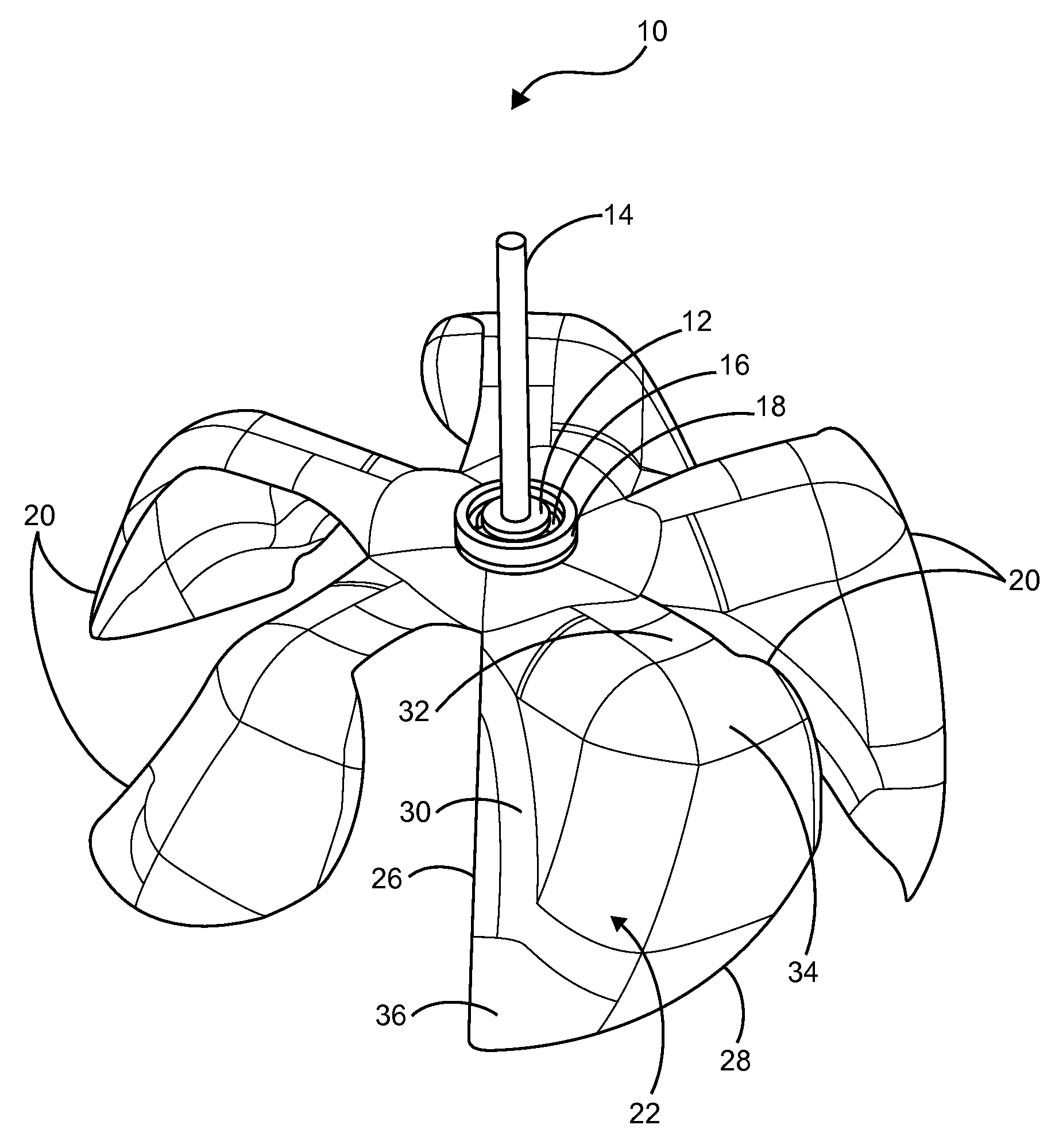
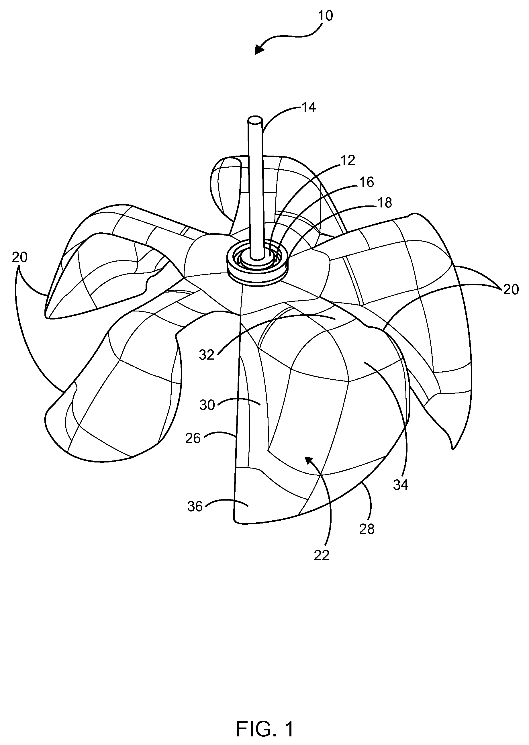
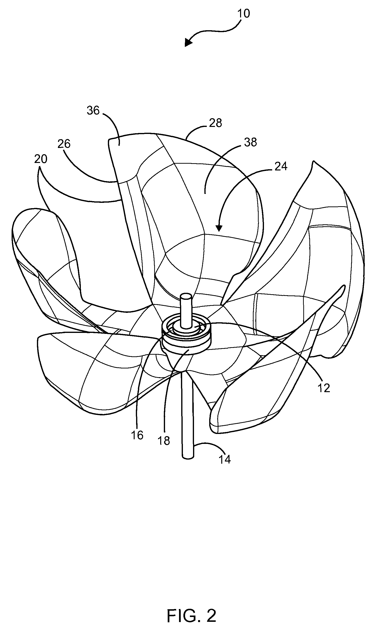
  • Uni-directional axial turbine blade assembly
  • Uni-directional axial turbine blade assembly
  • Uni-directional axial turbine blade assembly

Examples


Embodiment Construction

[0023]The following describes example embodiments in which the present invention may be practiced. This invention, however, may be embodied in many different ways, and the description provided herein should not be construed as limiting in any way. Among other things, the following invention may be embodied as methods or devices. As such, the present invention may take the form of an entirely hardware embodiment, an entirely software embodiment, or an embodiment combining software and hardware aspects. The following detailed descriptions should not be taken in a limiting sense.

[0024]In this document, the terms “a” or “an” are used, as is common in patent documents, to include one or more than one. In this document, the term “or” is used to refer to a nonexclusive “or,” such that “A or B” includes “A but not B,”“B but not A,” and “A and B,” unless otherwise indicated. Furthermore, all publications, patents, and patent documents referred to in this document are incorporated by referenc...


PUM


Abstract

A uni-directional axial turbine blade assembly comprises a central disc member coupled to an elongated shaft of a motor or generator, a rotational support member mounted on outer circumference of the central disc member, an outer ring mounted on outer circumference of the rotational support member and a plurality of blade members spaced equidistantly, extending radially outward from the outer ring. Each blade member includes a straight leading edge, a curved trailing edge, an exterior surface including a first region having a curved surface, a second region having a flat surface and a convex surface extending from the flat surface and terminating to a radially inward portion and an interior surface including a third region having a concave surface. The preferred embodiment renders the formation of a unique blade configuration that facilitates uni-directional rotation of the blade assembly irrespective of changes in flow direction of fluid.

Description

CROSS-REFERENCE TO RELATED APPLICATIONS[0001]Not Applicable.STATEMENT REGARDING FEDERALLY SPONSORED RESEARCH AND DEVELOPMENT[0002]Not Applicable.FIELD OF THE DISCLOSURE[0003]This embodiment relates to turbine blade assemblies, and more particularly to a uni-directional axial turbine blade assembly used for propellers.DISCUSSION OF RELATED ART[0004]The uni-directional axial turbine blade assembly is widely used in propeller fans, impellers, wind turbines, hydro-tidal wave energy generators, hydro turbines, any industries involving rotation devices and the like. The uni-directional axial turbine blade assembly provides unidirectional rotation from bidirectional, or reversible fluid, or shifting wind directions. Generally, the unidirectional axial turbine blade assembly comprises a small number of blades arranged radially outward from a hub and is driven by horizontal shaft. This type of assembly can be used in cases where the blades rotate in one direction regardless of the direction ...

Claims


Application Information

Patent Timeline
Patent Type & Authority Patents(United States)
IPC IPC(8): F03D1/06F03B3/12F01D5/14F03B13/26
CPCF01D5/141F03D1/0633Y02T50/673F05B2210/404F03B13/264Y02E10/72Y02T50/60Y02E10/30Y02E10/20
Inventor SHAKIBAPOUR, MOHAMMAD ISMAIL ABBASSI
Owner SHAKIBAPOUR MOHAMMAD ISMAIL ABBASSI
Learn More