
Radar apparatus

a technology of radar and antenna, applied in the direction of reradiation, pedestrian/occupant safety arrangement, instruments, etc., can solve the problems of deteriorating yield and performance, increasing the complexity of the transmission/reception circuit unit and the radar size, and increasing the number of antennas and channels for satisfying such requirements. , to achieve the effect of suppressing the deterioration of yield and performance and reducing the siz

Active Publication Date: 2015-12-08
HL KLEMOVE CORP
View PDF26 Cites 0 Cited by
  • Summary
  • Abstract
  • Description
  • Claims
  • Application Information

AI Technical Summary

Benefits of technology

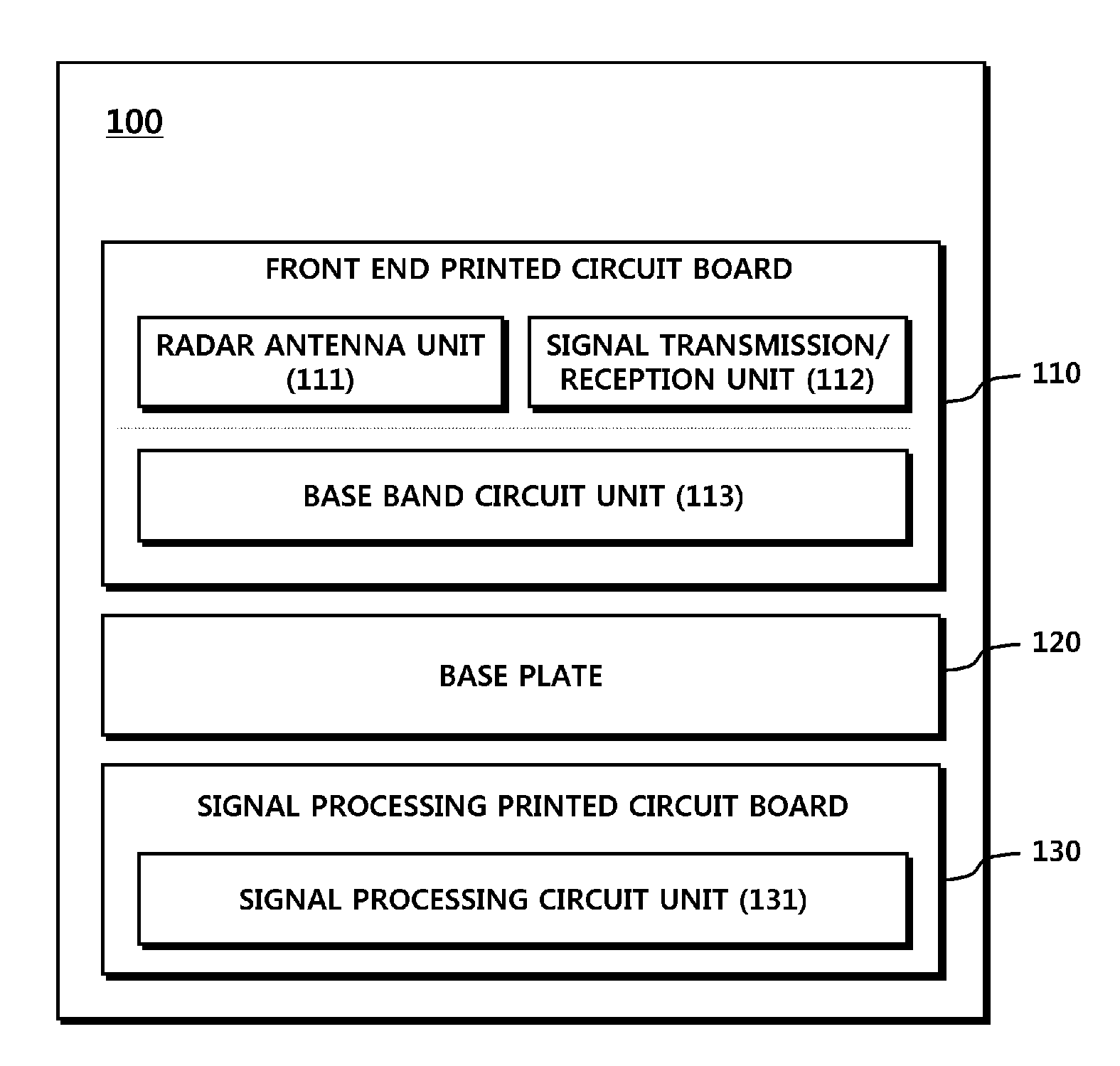
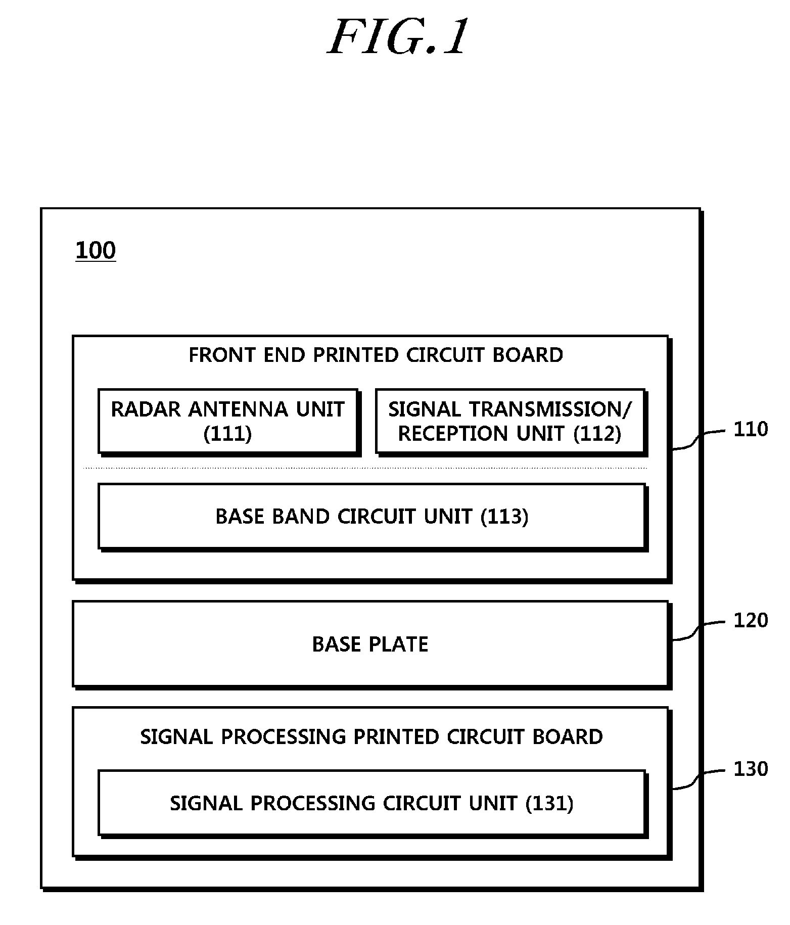
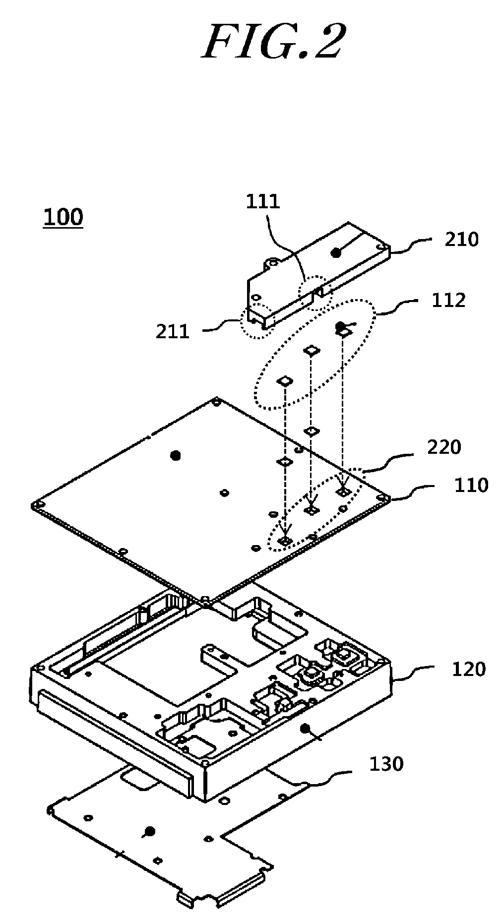
The present invention is aimed at solving the problems of prior radar apparatuses by providing a front end structure that is small in size and has a reduced number of parts. Additionally, the invention seeks to prevent the deterioration of the yield and performance of the radar apparatus. Overall, the invention offers a front end structure that meets both size and performance requirements.

Problems solved by technology

The number of antennas and the channels of the transmission / reception unit for satisfying such requirements should unavoidably be increased.
Accordingly, there is a problem in that the complexity of a transmission / reception circuit unit and a radar size should be increased.
However, such a conventional configuration necessarily requires a transition circuit to convert an electric signal between the antenna and the transmission / reception unit circuit into a radio signal and a waveguide for transmitting the radio signal, which causes a problem of deteriorating a yield and performance in addition to a problem of increasing the size of the radar apparatus.

Method used


Image

  • Radar apparatus
  • Radar apparatus
  • Radar apparatus

Examples


Embodiment Construction

[0035]Hereinafter, exemplary embodiments of the present invention will be described with reference to the accompanying drawings. In the following description, the same elements will be designated by the same reference numerals although they are shown in different drawings. Further, in the following description of the present invention, a detailed description of known functions and configurations incorporated herein will be omitted when it may make the subject matter of the present invention rather unclear.

[0036]In addition, terms, such as first, second, A, B, (a), (b) or the like may be used herein when describing components of the present invention. Each of these terminologies is not used to define an essence, order or sequence of a corresponding component but used merely to distinguish the corresponding component from other component(s). It should be noted that if it is described in the specification that one component is “connected,”“coupled” or “joined” to another component, a t...


PUM


Abstract

The present invention relates to a radar apparatus. More particularly, the present invention is a radar apparatus having a front end structure that is reduced in size and the number of parts.

Description

CROSS-REFERENCE TO RELATED APPLICATION[0001]This application claims priority from and the benefit under 35 U.S.C. §119(a) of Korean Patent Application No. 10-2012-0023869, filed on Mar. 8, 2012 which is hereby incorporated by reference for all purposes as if fully set forth herein.BACKGROUND OF THE INVENTION[0002]1. Field of the invention[0003]The present invention relates to a radar apparatus.[0004]2. Description of the Prior Art[0005]Vehicle radar technologies for implementing an advanced vehicle safety system for protecting humans' lives and properties are increased in the applicability thereof from a front side to a rear side of a vehicle day by day.[0006]Radar systems for implementing such an application use superhigh frequency bands of 24 GHz and 77 GHz as sensing signals. Recently, for the purpose of beam-forming for improving angular resolution, it is essential to arrange a plurality of reception channels in a transmission / reception unit circuit configuration, and occasional...

Claims


Application Information

Patent Timeline
Patent Type & Authority Patents(United States)
IPC IPC(8): G01S13/00G01S7/02G01S7/03G01S13/02G01S13/93H01Q1/32H01Q21/28G01S13/931
CPCG01S13/00G01S7/032G01S13/931G01S2007/027H01Q1/3233H01Q21/28G01S7/027G01S13/93G01S13/06B60R21/013B60W30/08
Inventor CHOI, SEUNG UNKIM, MIN SEOKJEONG, SEONG HEELEE, JAE EUN
Owner HL KLEMOVE CORP
Learn More