Device for monitoring the position and movement of a brake pedal

a technology for monitoring the position and movement of the brake pedal, which is applied in the direction of braking systems, rotary clutches, fluid couplings, etc., can solve the problems of disadvantageous assembly process and number of components of known devices, and achieve the effect of simple assembly and reduced number of components

Active Publication Date: 2015-12-08
CONTINENTAL TEVES AG & CO OHG
View PDF15 Cites 0 Cited by
  • Summary
  • Abstract
  • Description
  • Claims
  • Application Information

AI Technical Summary

Benefits of technology

[0006]Therefore, an aspect of the invention provides a different device for monitoring the positions and movements of a brake pedal, which device is simple to assemble and comprises a reduced number of components.
[0007]This aspect is achieved in accordance with the invention by means of a device for monitoring the position and movement of a brake pedal for use within a servo-controlled brake system for motor vehicles, comprising a brake actuating unit having a brake power assist unit having a power assist unit housing that is divided into at least one vacuum chamber and at least one working chamber by means of at least one axially movable wall that can be influenced by a pneumatic differential pressure, wherein the movable wall is embodied as a membrane disk that is supported on a control valve housing and as a membrane that lies on said membrane disk, and said brake actuating unit having a master cylinder that is fastened to the brake power assist unit and comprises a housing and at least one piston that can be displaced in a linear manner within said master cylinder, and a position indicator for monitoring the position of the brake pedal, which position indicator transmits signals to a sensor element that can be connected to an electronic control unit, wherein the position indicator is provided on a support that is coupled to the movement of the control valve housing or to the movable wall that is supported by the control valve housing, which support is guided in a housing of a sensor element, and wherein the housing of the sensor element penetrates in a vacuum-tight manner the power assist unit housing and the housing of the master cylinder having a first housing section. This results in the advantage that during a maintenance service the housing of the sensor element and the position indicator can be replaced without a large expenditure.
[0008]The ability to replace the components can be achieved in accordance with an advantageous development of the invention in a simple manner, by virtue of the fact that the housing of the sensor element is provided on the housing of the master cylinder by means of a fastening means in such a manner that it can be dismantled.
[0011]In accordance with an advantageous embodiment of the invention, the housing of the sensor element having a second housing section protrudes out of the brake actuating unit, wherein the sensor element is arranged in the second housing section, on which a plug connector element is formed in order to provide the connection to the electronic control unit. The sensor element can therefore be connected to the electronic control unit in a simple manner. Furthermore, the arrangement of the housing of the sensor element has proven to be optimal with regard to packaging.
[0016]In this case, a further magnet can preferably be provided for coupling the movement of the position indicator, which magnet is arranged on a second end of the support and is connected to the support by means of a pressed connection. This arrangement of the further magnet additionally improves the compensation of the component tolerances.

Problems solved by technology

The known devices are regarded as disadvantageous with regards to the assembly process and the number of components.

Method used


Image

  • Device for monitoring the position and movement of a brake pedal
  • Device for monitoring the position and movement of a brake pedal
  • Device for monitoring the position and movement of a brake pedal

Examples


Embodiment Construction

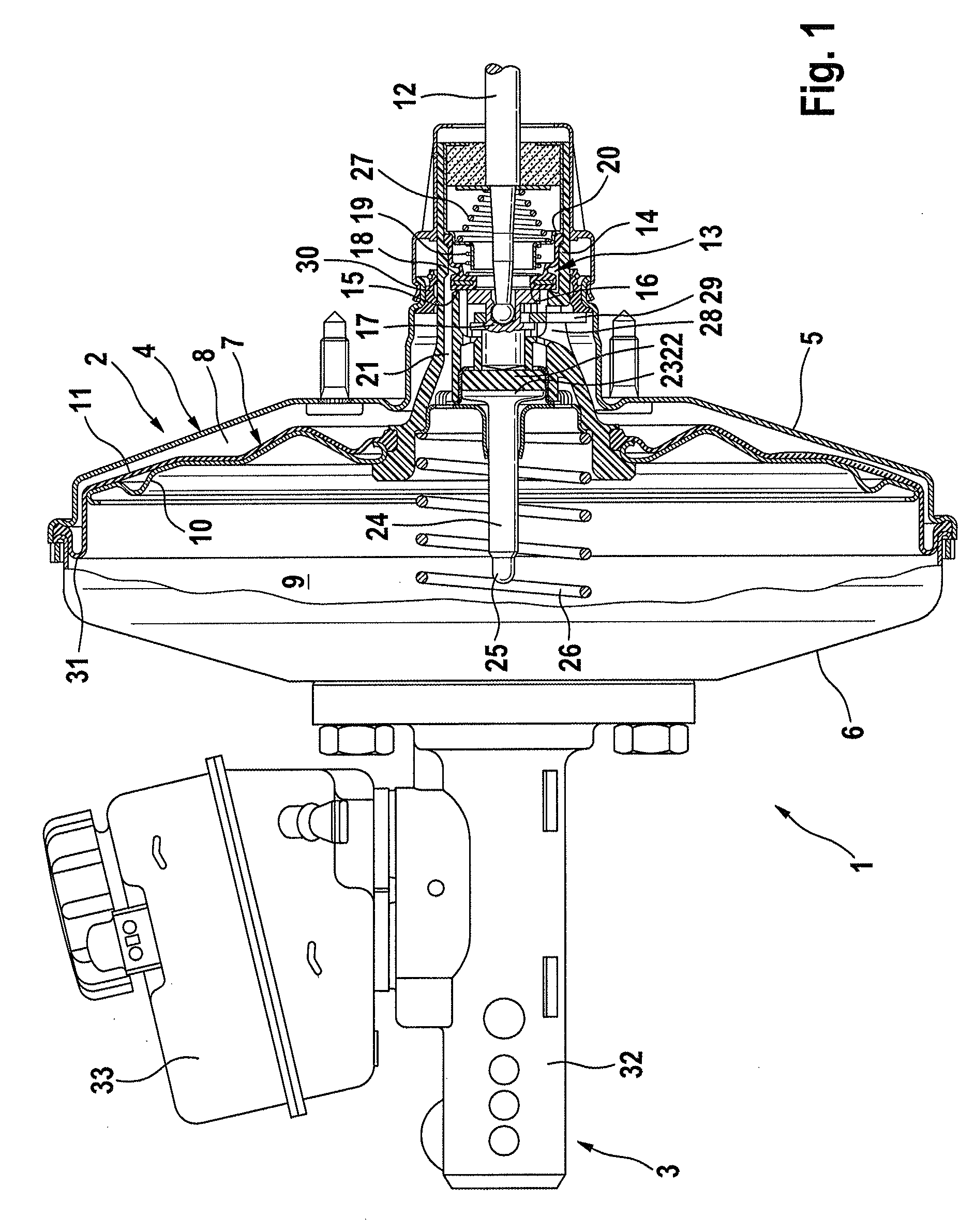
[0025]FIG. 1 illustrates a longitudinal sectional view of a known brake actuating unit 1 having a brake power assist unit 2 and a master cylinder 3 of a motor vehicle brake system, which master cylinder is fastened to said brake power assist unit, which motor vehicle brake system can be used in an application in accordance with the invention for monitoring the positions and movements of a brake pedal.

[0026]A merely schematically indicated power assist unit housing 4 of the brake power assist unit 2 comprises a first housing half shell 5 and a second housing half shell 6, which with the aid of measures that use shaping technology, by way of an example using a lance, are pressed together in a force-fitting manner. The power assist unit housing 4 is divided into a working chamber 8 and a vacuum chamber 9 by means of an axially movable wall 7 that can be influenced by a pneumatic differential pressure. The axially movable wall 7 comprises a membrane disk 10, which is deep-drawn for exam...


PUM


Abstract

A device for monitoring the position and movement of a brake pedal for motor vehicles, including a power assist brake actuating unit. The brake actuating unit having a master cylinder fastened to the brake power assist unit, a housing and at least one piston displaceable in a linear manner in the master cylinder, and a position indicator for monitoring the position of the brake pedal. The position indicator transmits signals to a sensor element connected to an electronic control unit. The position indicator is provided on a support coupled to the movement of the control valve housing or to the movable wall that is supported by the control valve housing. The support is guided in a housing of a sensor element, and the housing of the sensor element penetrates in a vacuum-tight manner the power assist unit housing and the housing of the master cylinder having a first housing section.

Description

CROSS REFERENCE TO RELATED APPLICATIONS[0001]This application is the U.S. National Phase Application of PCT / EP2011 / 062889, filed Jul. 27, 2011, which claims priority to German Patent Application No. 10 2010 062 163.3, filed Nov. 30, 2010, the contents of such applications being incorporated by reference herein.BACKGROUND OF THE INVENTION[0002]Devices for monitoring the positions and movements of a brake pedal are generally known.[0003]DE 10 2008 020 A1, which is incorporated by reference, discloses by way of an example a master cylinder arrangement having a piston, in which arrangement the piston is permanently coupled to a position sensing rod in order for the two parts to move in conjunction with one another. The rod is guided in a displaceable manner in a guide shaft in the cylinder housing, which guide shaft extends parallel to a first cylinder bore and comprises a position sensing member for sensing the position of said rod by means of a position measuring sensor.[0004]Furtherm...

Claims


Application Information

Patent Timeline
Patent Type & Authority Patents(United States)
IPC IPC(8): B60T11/18B60Q1/44F15B15/20B60T7/04B60T13/52B60T17/22
CPCF15B15/20B60Q1/441B60T7/042B60T11/18B60T13/52B60T17/22B60Q1/44
Inventor KONIG, HARALDRUFFER, MANFRED
Owner CONTINENTAL TEVES AG & CO OHG
Why Eureka
Try Eureka