
Closing hinge

a hinge and hinge body technology, applied in the field of closing hinges, can solve the problems of laborious production, impaired handling impair the appearance of the door arrangement, so as to improve the closing characteristic, improve the closing force, and improve the effect of reliable door closing

Inactive Publication Date: 2015-12-08
SUSPA
View PDF24 Cites 13 Cited by
  • Summary
  • Abstract
  • Description
  • Claims
  • Application Information

AI Technical Summary

Benefits of technology

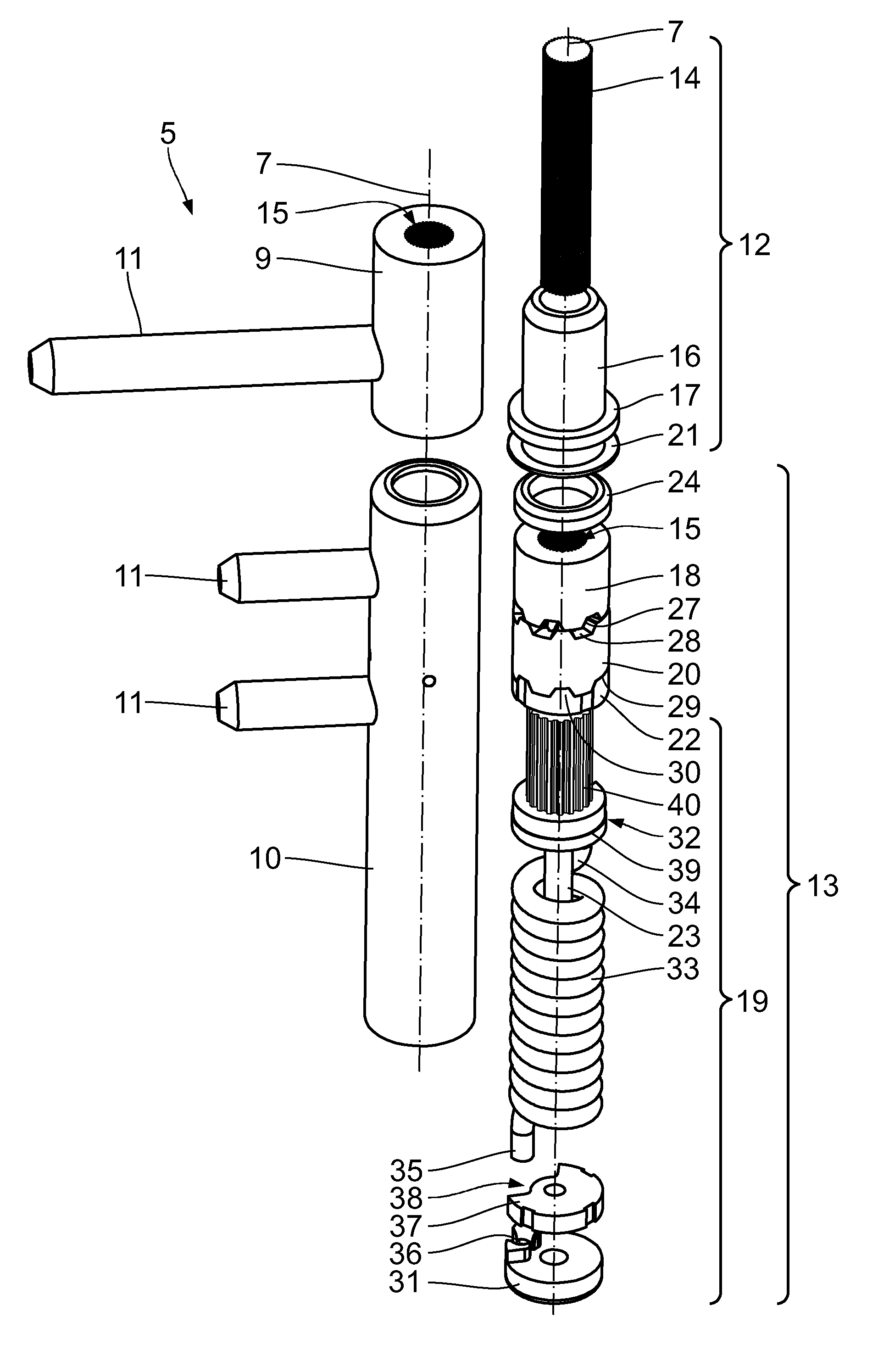
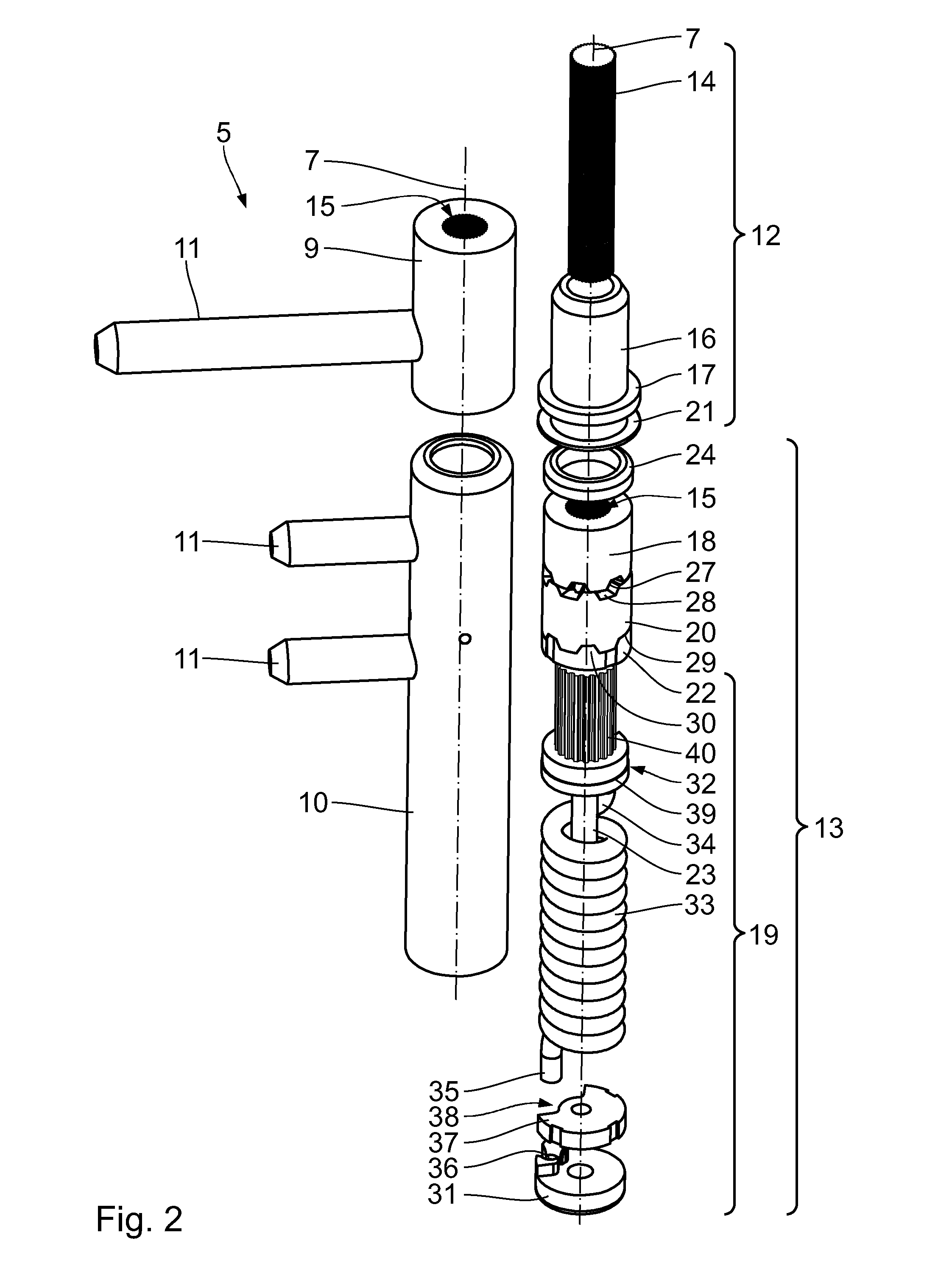
[0008]The closing hinge, because of the arrangement of the rotating receiver unit and the freely rotating closing unit concentrically with respect to the center longitudinal axis, allows a compact arrangement of the components in a closing hinge. Moreover, the closing hinge allows the rotating receiver unit to be coupled or decoupled to / from the freely rotating closing unit. It is therefore possible to deactivate the closing function of the closing hinge, in particular at large pivoting angles, during a pivoting of the first part in relation to the second part.
[0020]A closing hinge, comprising a further freely rotating closing unit, has an improved closing characteristic. Since an additional freely rotating closing unit is provided, a further torsion spring can be activated connected during the opening or closing, in particular of a door. In particular it is possible to switch the second freely rotating closing unit separately from the first freely rotating closing unit. In particular, one of the two freely rotating closing units allows an activation of the second torsion spring in a small angle range, i.e. shortly before a door leaf rests on a door frame. It is thus advantageously possible to ensure reliable closing of the door and, in particular to apply an increased closing force due to overcoming a catch on the lock and a compression of a seal. At the same time it is ensured that when the door is opened, this increased closing force only has to be overcome in a small rotation angle range. In particular, this angle range is less than 10°, in particular less than 5° and in particular less than 2°. This opening angle range can, in particular, be adjusted.

Problems solved by technology

A closing system of this type is laborious to produce and impairs the appearance of a door arrangement of this type.
The handling of the door arrangement is impaired, as the closing system projects into the opening region of the door.

Method used


Image

  • Closing hinge
  • Closing hinge
  • Closing hinge

Examples


first embodiment

[0108]The damping hinge 6 will be described in more detail below in accordance with a first embodiment with the aid of FIGS. 8 to 11. The damping hinge 6 has a hollow cylindrical damping hinge housing 47 with respect to a rotational axis 46, with a damping hinge housing lower part 48 and a damping hinge housing upper part 49. The damping hinge 6 is also called a band with the damping function. The band with the damping function has the two housing parts 48, 49 and is configured as a two-part band. The damping hinge 6 is arranged with the rotational axis 46 concentrically with respect to the pivot axis 4 of the door arrangement 1. In accordance with the closing hinge 5, the damping hinge 6 also has a cylindrical housing 47 with an external diameter of 16 mm and a length along the rotational axis 46 of 130 mm. A housing 47 of this type substantially corresponds to the housing size of a hinge used as standard to connect a door leaf to a door frame. The use of the closing hinge 5 and th...

fourth embodiment

[0145]a damping hinge will be described below with reference to FIGS. 19 to 23. Structurally identical parts receive the same reference numerals as in the first three embodiments, to the description of which reference is hereby made. Structurally different, but functionally similar parts receive the same reference numerals with a “c” placed thereafter.

second embodiment

[0146]The damping hinge 6c is configured as a three-part band like the damping hinge 6b according to the The essential difference compared to the above-described embodiments is that the profile portion 52c provided in the damping hinge housing upper part 49c has an entraining portion 87 and a freely running portion 88 arranged in an adjacent manner along the rotational axis 46. The entraining portion 87 is configured in such a way that it has a cross-section, which is oriented perpendicular to the rotational axis 46 and has a non-round internal contour 89 with respect to the rotational axis 46. The non-round internal contour 89 corresponds with the external contour of the rotating entrainer arranged on the axial element 63c, which has three entrainer webs 78 directed radially outwardly along the outer periphery with respect to the rotational axis 46. Since the external contour of the rotating entrainer with the entrainer webs 78 corresponds to the internal contour 89, the axial ele...


PUM


Abstract

A closing hinge for the pivotable articulation of a first part, in particular a door leaf, on a second part, in particular a door frame, includes a center longitudinal axis, a rotating receiver unit that can be rotated about the center longitudinal axis for fastening to the first part, which can be rotated, in particular, about the center longitudinal axis, and a freely rotating closing unit, which is connected to the rotating receiver unit in a torque-transmitting manner, for fastening to the second part, which is fixed, in particular, with respect to the center longitudinal axis, the closing hinge being displaceable between a closing arrangement and a freely rotating arrangement, the rotating receiver unit being freely rotatable, in particular in a torque-free manner, about the center longitudinal axis relative to the freely rotating closing unit in the closing arrangement.

Description

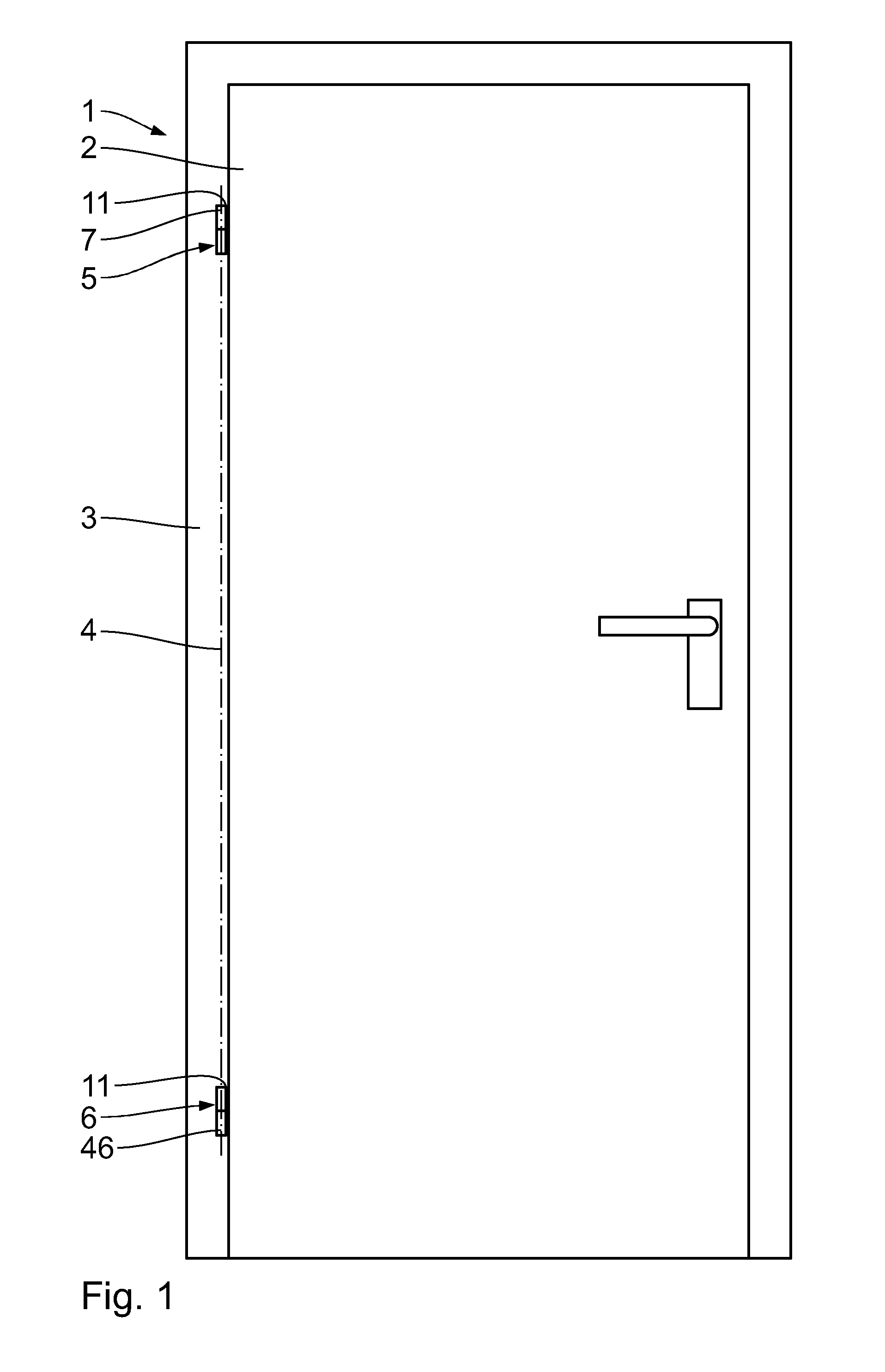
CROSS-REFERENCE TO RELATED APPLICATIONS[0001]This application is a United States National Phase Application of International Application PCT / EP2012 / 056184 filed Apr. 4, 2012 and claims the benefit of priority under 35 U.S.C. §119 of German Patent Application DE 10 2011 007 400.7 filed Apr. 14, 2011, the entire contents of which are incorporated herein by reference.FIELD OF THE INVENTION[0002]The invention relates to a closing hinge for the pivotable articulation of a first part, in particular a door leaf, on a second part, in particular a door frame.BACKGROUND OF THE INVENTION[0003]A door arrangement with a closing device, which, for example has a gear drive with a slide rail, which are in each case arranged on an upper side of a door leaf and a door frame, is known from public prior use. A closing system of this type is laborious to produce and impairs the appearance of a door arrangement of this type. The handling of the door arrangement is impaired, as the closing system projects...

Claims


Application Information

Patent Timeline
Patent Type & Authority Patents(United States)
IPC IPC(8): E05F3/22E05F1/14E05F3/20E05F1/12
CPCE05F1/1207E05F1/1215E05F3/20E05Y2900/132Y10T16/53888
Inventor NAGL, WOLFGANGSTEPHAN, FLORIANMULLER, HERBERT
Owner SUSPA
Learn More