
Outline approximation for point cloud of building

a technology of building outline and point cloud, applied in the field of point cloud data, can solve the problems of no design bim for most existing buildings, labor-intensive and error-prone creation process, and crucial and difficult building reconstruction steps

Active Publication Date: 2015-11-17
AUTODESK INC
View PDF3 Cites 3 Cited by
  • Summary
  • Abstract
  • Description
  • Claims
  • Application Information

AI Technical Summary

Benefits of technology

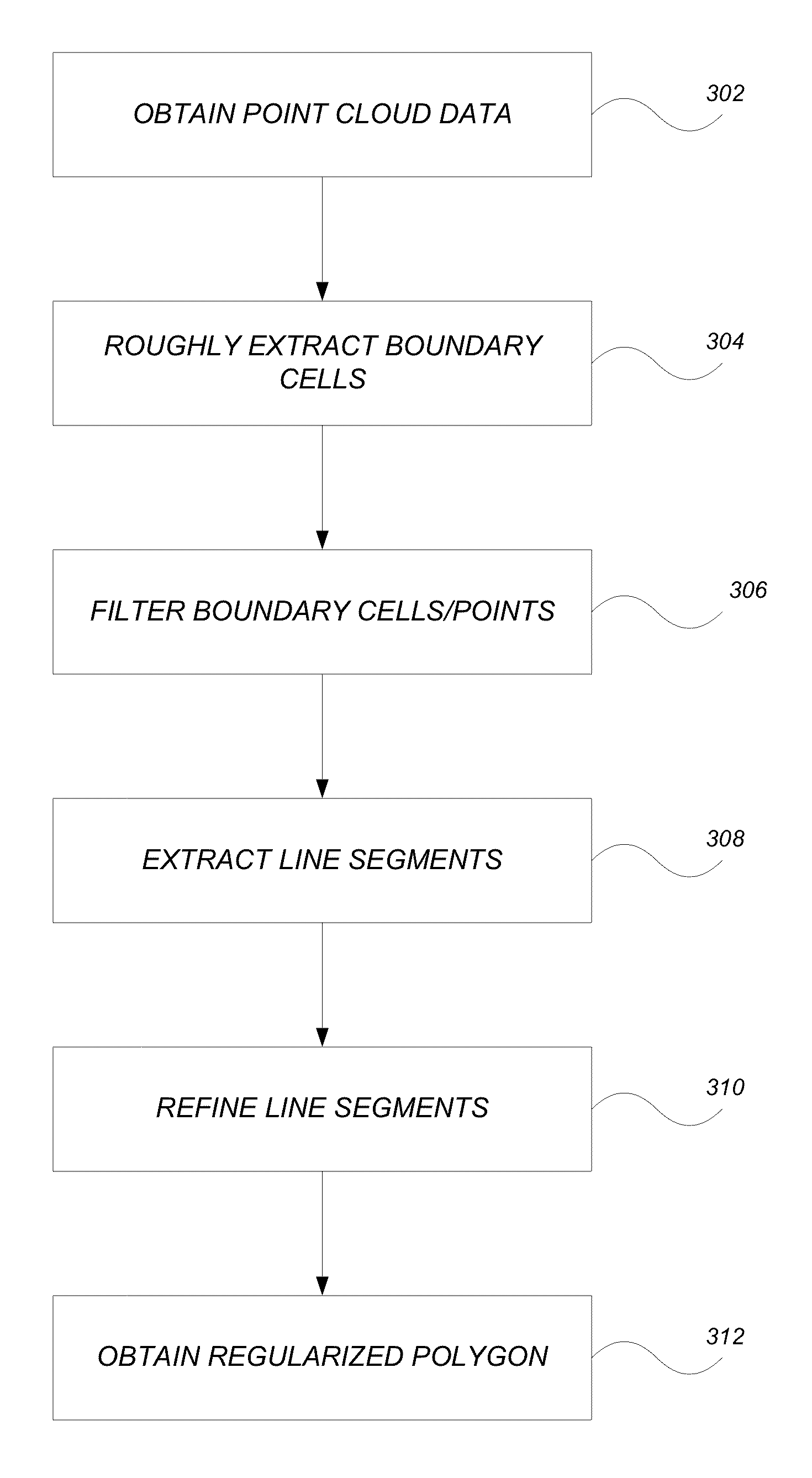
The invention provides a way to create a model of the boundaries of points from a building scan. This can be used to create a floor plan or outline of an entire building. The process uses a method called flood filling to extract the boundaries of points, and then filters through them to get the potential boundary points. These points are then refined to create a regularized polygon that matches the shape of the building. This method works well with different types of point sources.

Problems solved by technology

However, no design BIM exists for most existing buildings.
This creation process is labor-intensive and error-prone.
However, a boundary determination based on points obtained via a scan of a building is a crucial and difficult step in the building reconstruction task.
One reason for the difficulty is that laser scanners have some difficulty in the as-built environment to capture low-reflectance surfaces (e.g., anything painted black), specular surfaces (e.g., shiny metal and mirrors), and transparent or translucent surfaces (e.g. windows), which results in the presence of concavity in the building boundary [Huber 2010].
Moreover, point clouds are often composed of multiple scans with noise and points of non-uniform point density, which will also cause difficulty in a boundary determination.
However, this approach is not very successful in experiments because the distribution of the used points is far from even.
This method is computationally complex, and its performance depends on the parameter alpha.
Although methods for line simplification (such as Douglas-Peucker) can be applied during the generalization process, this category of boundary extraction methods doesn't take the regular shape characteristics existing in most common buildings into consideration, and thus cannot generate satisfying outline results that can be used for as-built building modeling.
This is done recursively, thus enabling different shapes of buildings like L, T or U-shaped outlines, which limits the generality of Dutter's method.

Method used


Image

  • Outline approximation for point cloud of building
  • Outline approximation for point cloud of building
  • Outline approximation for point cloud of building

Examples


Embodiment Construction

[0029]In the following description, reference is made to the accompanying drawings which form a part hereof, and which is shown, by way of illustration, several embodiments of the present invention. It is understood that other embodiments may be utilized and structural changes may be made without departing from the scope of the present invention.

Hardware Environment

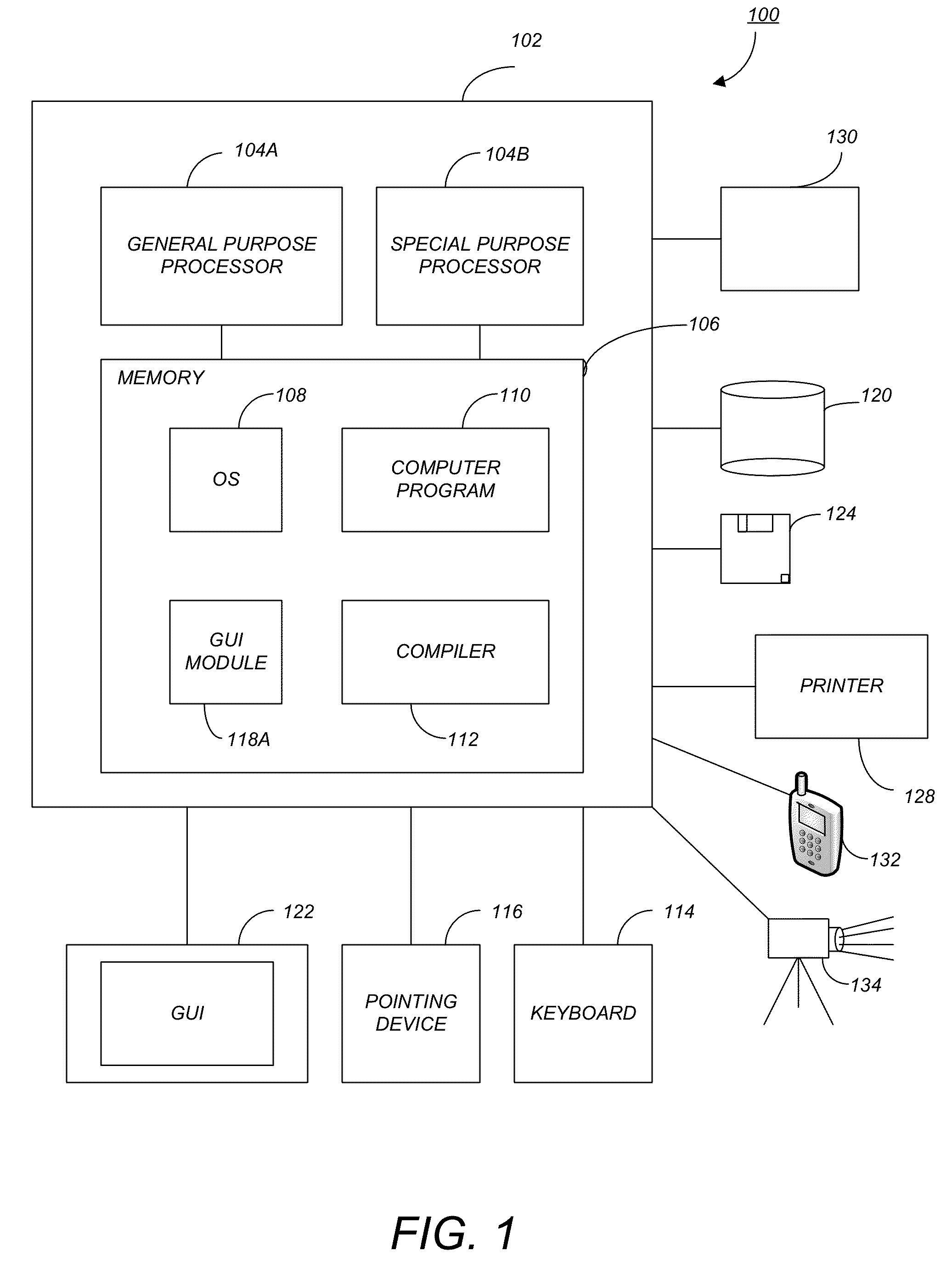
[0030]FIG. 1 is an exemplary hardware and software environment 100 used to implement one or more embodiments of the invention. The hardware and software environment includes a computer 102 and may include peripherals. Computer 102 may be a user / client computer, server computer, or may be a database computer. The computer 102 comprises a general purpose hardware processor 104A and / or a special purpose hardware processor 104B (hereinafter alternatively collectively referred to as processor 104) and a memory 106, such as random access memory (RAM). The computer 102 may be coupled to, and / or integrated with, other devices, in...


PUM


Abstract

A method, apparatus, system, and computer program product provide the ability to model a polyline boundary from point cloud data. Point cloud data is obtained and boundary cells are extracted. Potential boundary points are filtered from the boundary cells. Line segments are extracted from the potential boundary points and refined. A regularized polygon is obtained by intersecting the refined line segments.

Description

CROSS-REFERENCE TO RELATED APPLICATIONS[0001]This application is related to the following co-pending and commonly-assigned patent application, which application is incorporated by reference herein:[0002]U.S. patent application Ser. No. 13 / 399,158, entitled “SEGMENTATION OF GROUND-BASED LASER SCANNING POINTS FROM URBAN ENVIRONMENT”, by Yan Fu and Jin Yang, filed on Feb. 17, 2012;[0003]U.S. patent application Ser. No. 12 / 849,647, entitled “PIPE RECONSTRUCTION FROM UNORGANIZED POINT CLOUD DATA”, by Yan Fu, Xiaofeng Zhu, Jin Yang, and Zhenggang Yuan, filed on Aug. 3, 2010, now U.S. Pat. No. 8,605,093, issued on Dec. 10, 2013, which application claims priority to Provisional Application Ser. No. 61 / 353,486, filed Jun. 10, 2010, by Yan Fu, Xiaofeng Zhu, Jin Yang, and Zhenggang Yuan, entitled “PIPE RECONSTRUCTION FROM UNORGANIZED POINT CLOUD DATA”; and[0004]U.S. patent application Ser. No. 12 / 849,670, entitled “PRIMITIVE QUADRIC SURFACE EXTRACTION FROM UNORGANIZED POINT CLOUD DATA”, by Yan...

Claims


Application Information

Patent Timeline
Patent Type & Authority Patents(United States)
IPC IPC(8): G06K9/48G06T7/00
CPCG06T7/0085G06T2207/10028G06T7/13G06V20/64
Inventor FU, YAN
Owner AUTODESK INC
Learn More