
Self-propelled civil engineering machine and method of controlling a civil engineering machine

a self-propelled, civil engineering machine technology, applied in the direction of roads, highway maintenance, transportation and packaging, etc., can solve the problems of difficult estimation of the exact position of the discontinuity by the machine driver, the disadvantage of the changeover to various different sensing members, and the inability to accurately control the self-propelled civil engineering machine. achieve the effect of improving the automatic control of the self-propelled civil engineering machin

Active Publication Date: 2015-11-10
WIRTGEN GMBH
View PDF60 Cites 14 Cited by
  • Summary
  • Abstract
  • Description
  • Claims
  • Application Information

AI Technical Summary

Benefits of technology

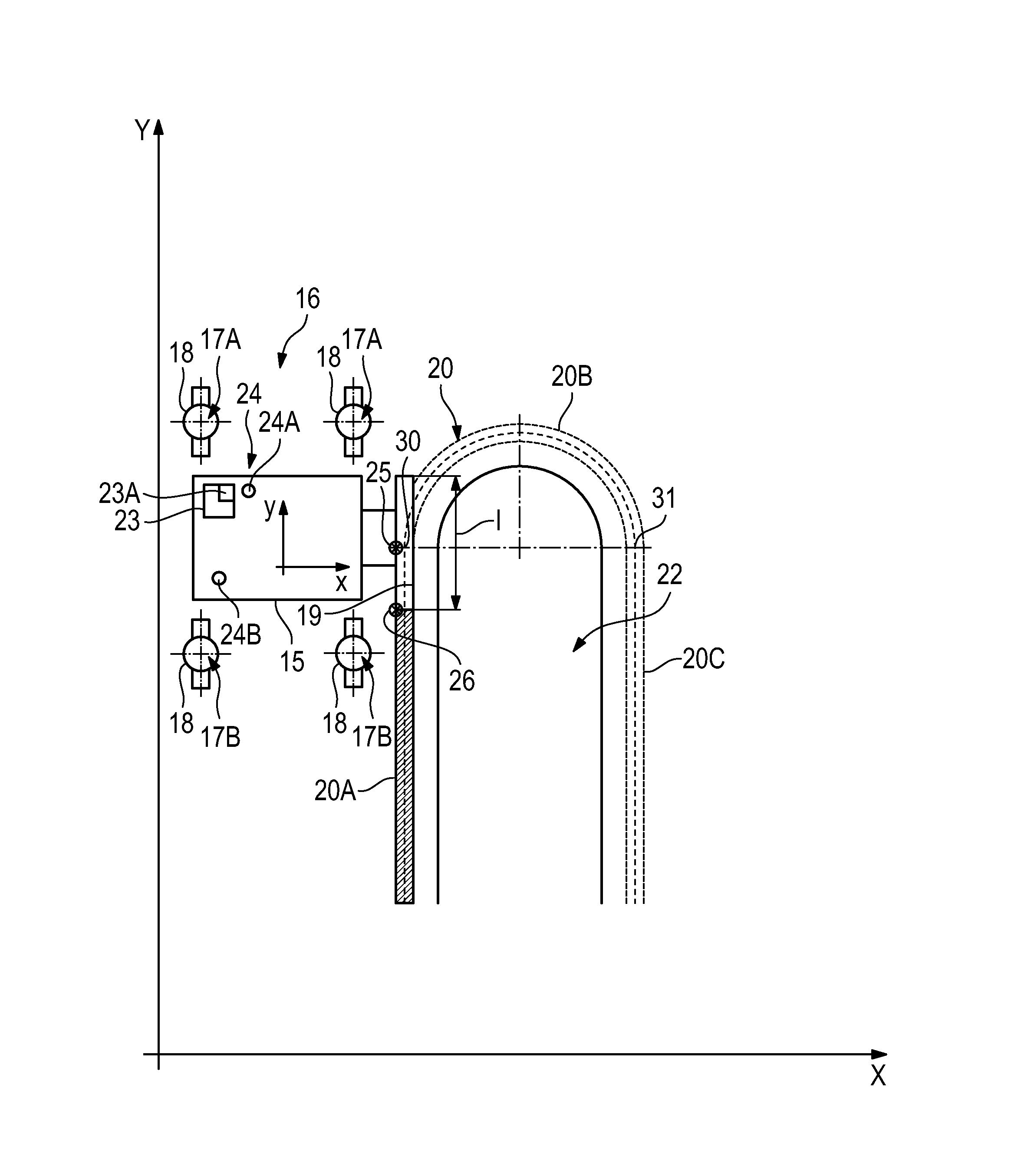
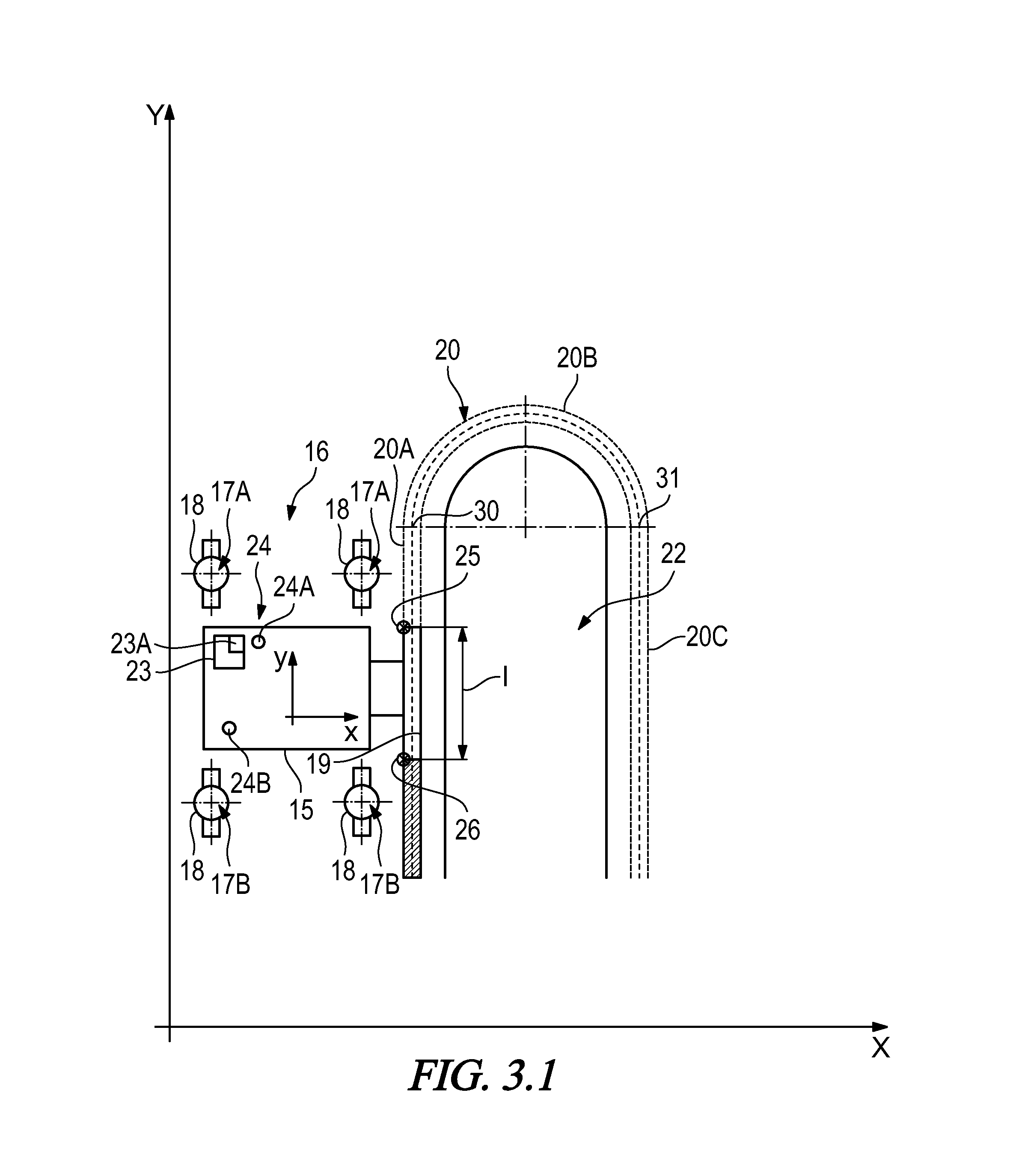
[0016]The object underlying the invention is to improve the automatic control of a self-propelled civil engineering machine particularly when the civil engineering machine is moving from a substantially straight section of the preset distance or path of travel onto a curved section thereof.

Problems solved by technology

A changeover to various different sensing members proves to be a disadvantage simply because the changeover means that the process is not a continuous one.
It is also a disadvantage that, when travel through a curve is controlled by the central sensing member, the position of the sensing member depends on the radius of the curve.
If however the slipform paver is to change its direction of operation at the transition from a straight section to a curved section, then problems arise in practice when the drive unit is controlled in the known way where provision is made for a changeover from the front and rear sensing members to the central sensing member at the entry into the curve.
What is a particular problem for the control system in this case is entry into tight curves, such for example as when concrete components in the form of traffic islands are being produced.
It has also been found that the transition from the straight section of the desired distance or path of travel to the curved section is a particular problem for the control of the civil engineering machine, because the position of the discontinuity is not precisely known.
However, the exact position of the discontinuity is difficult for the driver of the machine to estimate.
Even if the changeover should take place at exactly the right point in time, what results in practice will be an abrupt steering command because it is most unlikely that the central reference point will be at exactly the same spacing from the string line as the front and / or rear reference point at the time of the changeover.

Method used


Image

  • Self-propelled civil engineering machine and method of controlling a civil engineering machine
  • Self-propelled civil engineering machine and method of controlling a civil engineering machine
  • Self-propelled civil engineering machine and method of controlling a civil engineering machine

Examples


Embodiment Construction

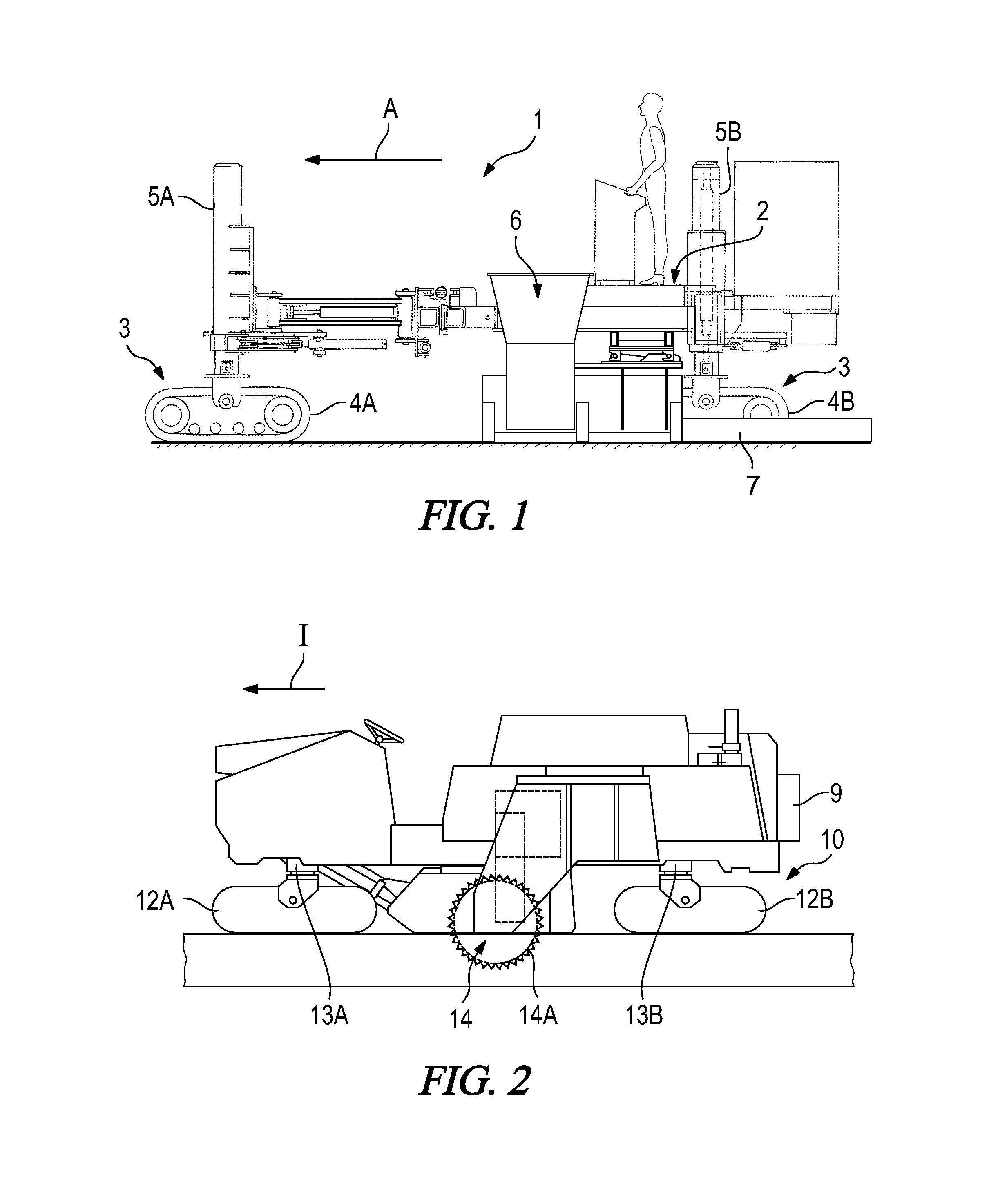
[0042]FIG. 1 is a view from the side of a slipform paver which serves as an example of a self-propelled civil engineering machine. Because slipform pavers as such are part of the prior art, all that will be described here are those components of the civil engineering machine which are material to the invention.

[0043]The slipform paver 1 has a chassis 2 which is carried by running gear 3. The running gear 3 has two front and two rear track-laying running-gear units 4A, 4B which are fastened to front and rear lifting columns 5A, 5B. The direction of operation (direction of travel) of the slipform paver is indicated by an arrow A.

[0044]The track-laying running-gear units 4A, 4B and the lifting columns 5A, 5B are part of a drive unit to enable the civil engineering machine to perform translatory and / or rotational movements on the ground. By raising and lowering the lifting columns 5A, 5B, the chassis 2 of the machine can be moved relative to the ground to adjust its height and inclinati...


PUM


Abstract

A civil engineering machine and a method of controlling the machine are based on the position of at least one reference point which is relevant to the control of the civil engineering machine being changed, as the civil engineering machine moves, as a function of a relative position of the at least one reference point relative to a desired path of travel.

Description

BACKGROUND OF THE INVENTION[0001]1. Field of the Invention[0002]The invention relates to a self-propelled civil engineering machine, and in particular a slipform paver, and to a method of controlling a self-propelled civil engineering machine.[0003]2. Description of the Prior Art[0004]There are a variety of known types of self-propelled civil engineering machine. Such machines include for example known slipform pavers or road milling machines. A distinguishing feature of self-propelled civil engineering machines is that they have a working unit which is arranged on a chassis of the machine and which has work-doing means for producing structures on a piece of ground or for changing the piece of ground.[0005]On known slipform pavers, the working unit comprises an arrangement for moulding flowable material, and in particular concrete, which will also be referred to below as a concrete mould. Structures of different configurations, such as crash barriers or traffic islands for example, ...

Claims


Application Information

Patent Timeline
Patent Type & Authority Patents(United States)
IPC IPC(8): E01C19/00E02F9/20E01C19/48
CPCE01C19/00E01C19/004E01C19/4886E02F9/2045B60W10/04B60W10/20B60W30/18B60W2300/17B60W2530/18B60W2710/20B60W2720/10E01C19/008
Inventor FRITZ, MATTHIASDAHM, MARTINBARIMANI, CYRUSHAHN, GUNTER
Owner WIRTGEN GMBH
Learn More