Carbon ion beam injector apparatus and method of use thereof
a technology of injector apparatus and carbon ion beam, which is applied in the field of solid cancer treatment, can solve the problems of reduced ability to repair damaged dna, increased risk of dna attack, and death of patients,
- Summary
- Abstract
- Description
- Claims
- Application Information
AI Technical Summary
Benefits of technology
Problems solved by technology
Method used
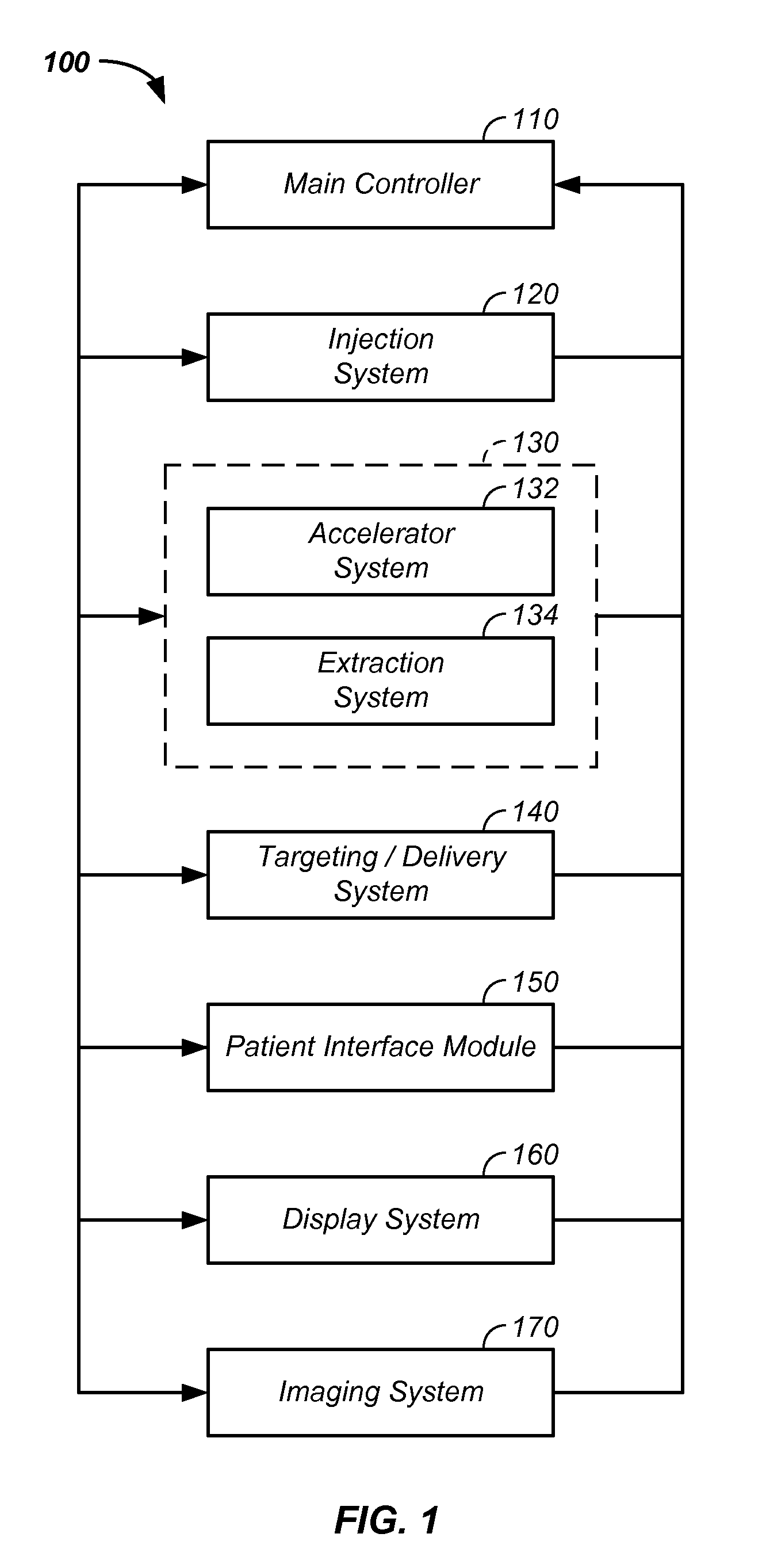
Image

Examples
Embodiment Construction
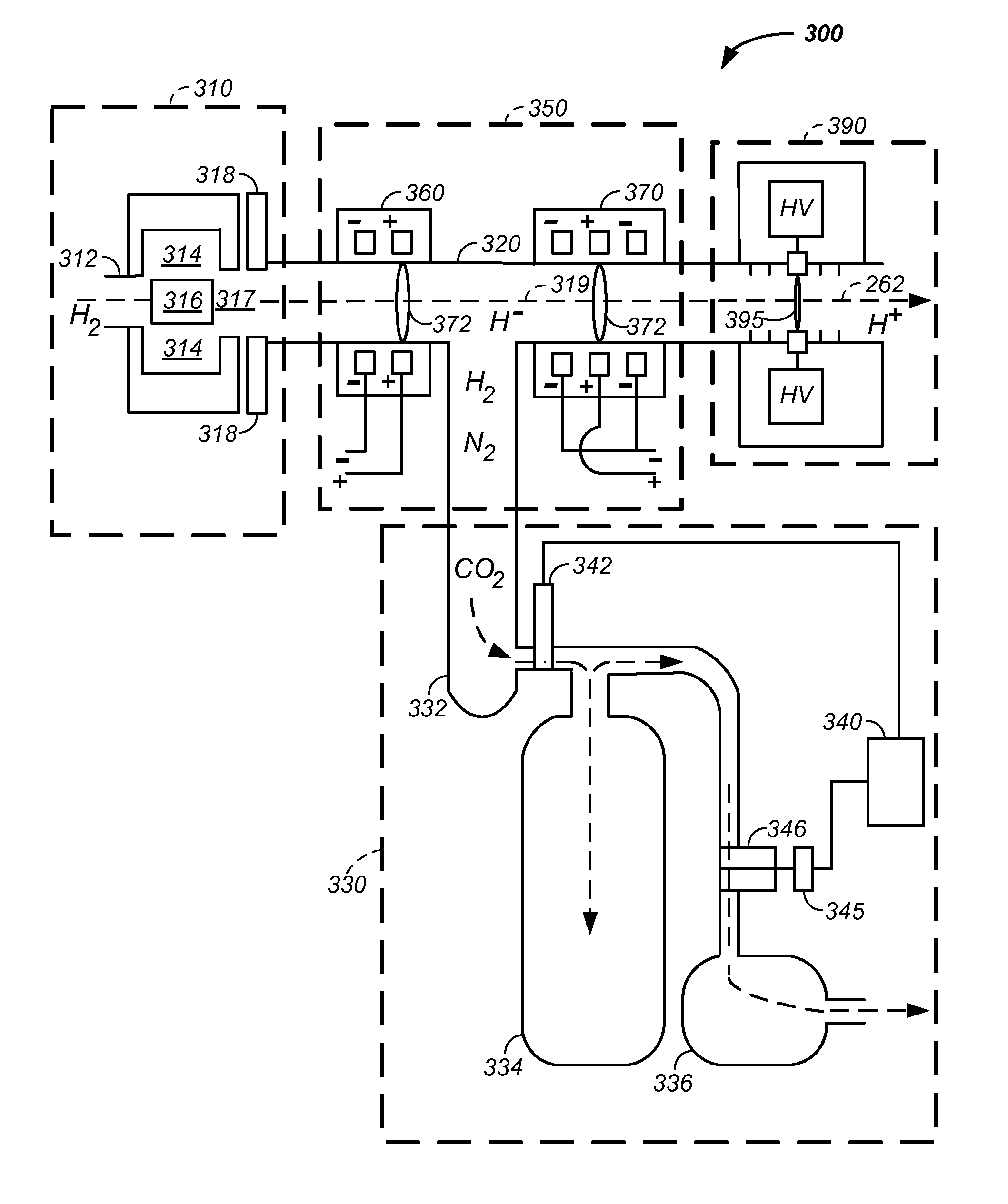
[0110]The invention comprises a method and apparatus used to form carbon cations, which are subsequently accelerated and used to treat a tumor.
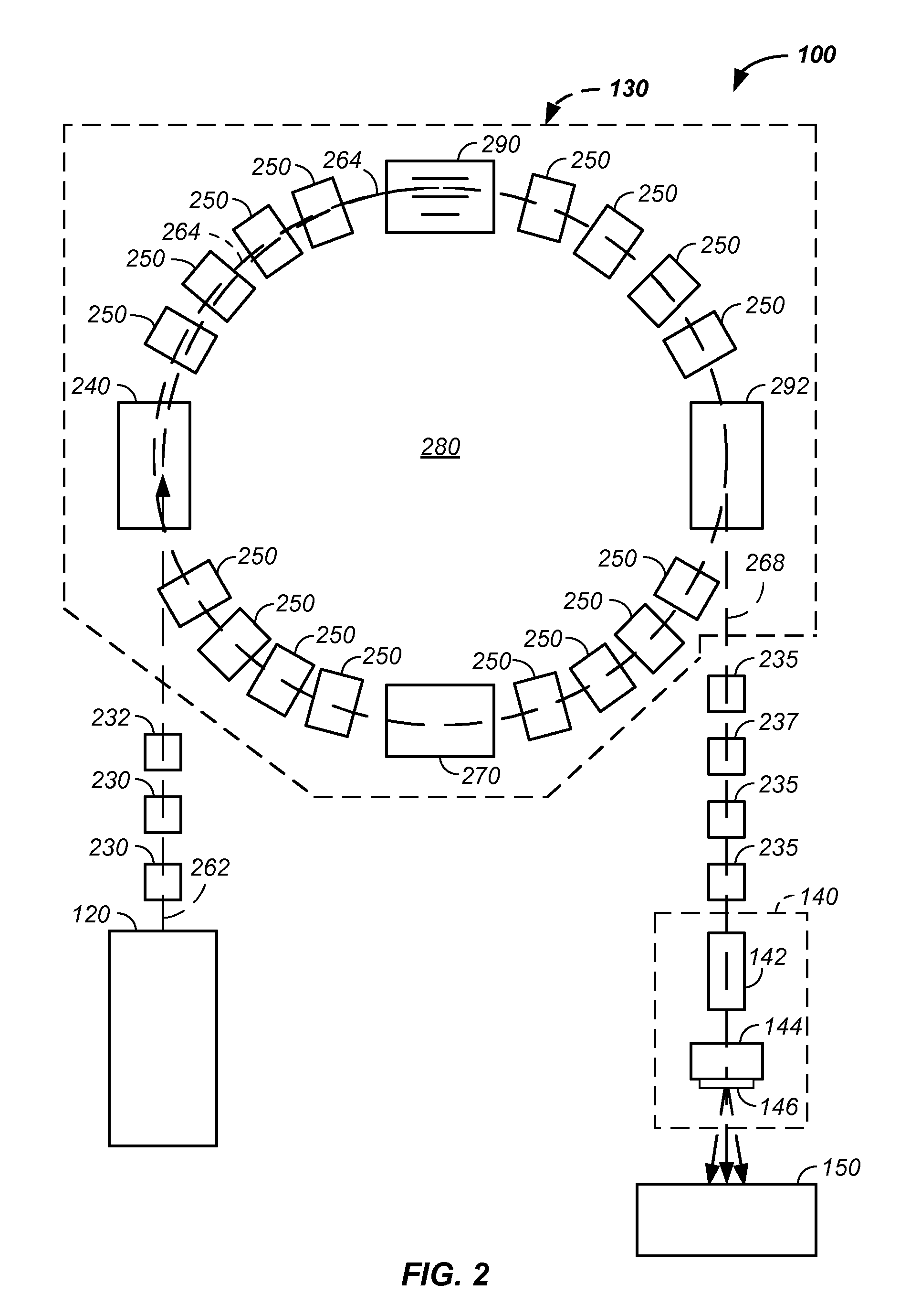
[0111]In one embodiment, a charged particle cancer therapy system is used to accelerate an anion, such a C−, and to convert the anion to a cation, such as C6+, through use of one or more electron extraction subsystems. A first example of an electron extraction subsystem is a hydrogen gas electron stripping system. A second example of an electron extraction subsystem is a carbon foil electron stripping system. The resultant cation is accelerated in a synchrotron, transported along a beam-line, and delivered to a tumor to ablate or destroy the tumor.
[0112]Used in combination with the invention, novel design features of a charged particle beam cancer therapy system are described. Particularly, a negative ion beam source with novel features in the negative ion source, ion source vacuum system, ion beam focusing lens, and tandem accelerator is des...
PUM
 Abstract
Description
Claims
Application Information
 - R&D
- Intellectual Property
- Life Sciences
- Materials
- Tech Scout
- Unparalleled Data Quality
- Higher Quality Content
- 60% Fewer Hallucinations
Browse by: Latest US Patents, China's latest patents, Technical Efficacy Thesaurus, Application Domain, Technology Topic, Popular Technical Reports.
© 2025 PatSnap. All rights reserved.Legal|Privacy policy|Modern Slavery Act Transparency Statement|Sitemap|About US| Contact US: help@patsnap.com