
Approach for controlling exhaust gas recirculation

a technology of exhaust gas and recirculation, which is applied in the direction of electrical control, machines/engines, output power, etc., can solve the problems of degrading combustion stability and limited amount of egr provided to the engine cylinder, so as to reduce the throttling of the engine, reduce the nox emission, and reduce the loss of pumping

Active Publication Date: 2015-11-03
FORD GLOBAL TECH LLC
View PDF15 Cites 1 Cited by
  • Summary
  • Abstract
  • Description
  • Claims
  • Application Information

AI Technical Summary

Benefits of technology

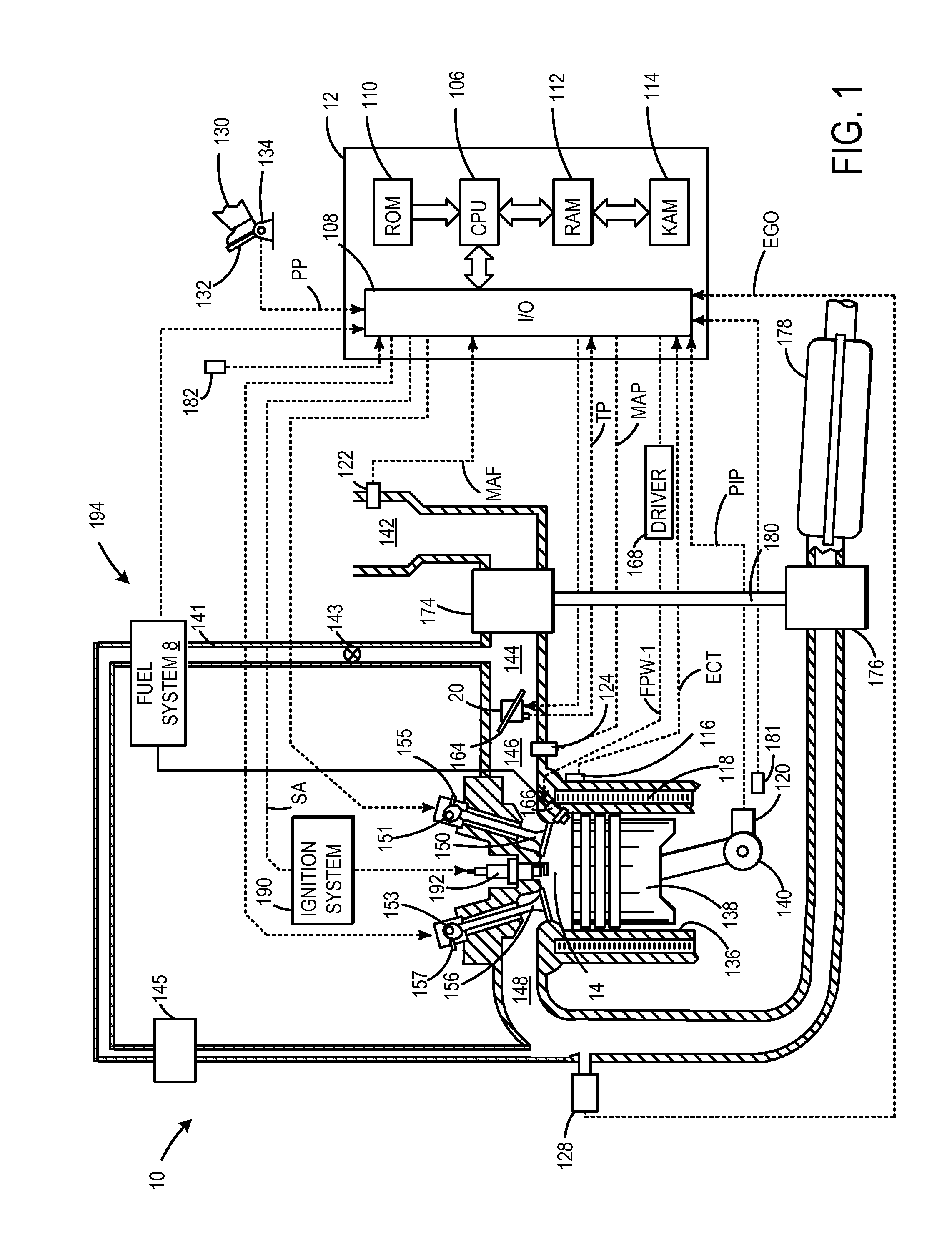
[0001]Engines may be configured with exhaust gas recirculation (EGR) systems to divert at least some exhaust gas from an engine exhaust passage to an engine intake passage. By controlling EGR to provide a desired engine dilution, engine pumping work, engine knock, as well as NOx emissions may be reduced. For example, at partial throttle operating conditions, providing EGR to the cylinders of the engine allows for the throttle to be opened to a greater extent for the same engine load. By reducing throttling of the engine, pumping losses may be reduced, thus improving fuel efficiency. Further, by providing EGR to the engine, combustion temperatures may be reduced (especially in implementations where EGR is cooled prior to being provided to the cylinders). Cooler combustion temperatures provide engine knock resistance, and thus increase engine thermal efficiency. Further still, EGR reduces a combustion flame temperature that reduces an amount of NOx generated during combustion. In one example, during a combustion cycle, all EGR and fuel is provided to cylinders of an engine after intake valve opening.
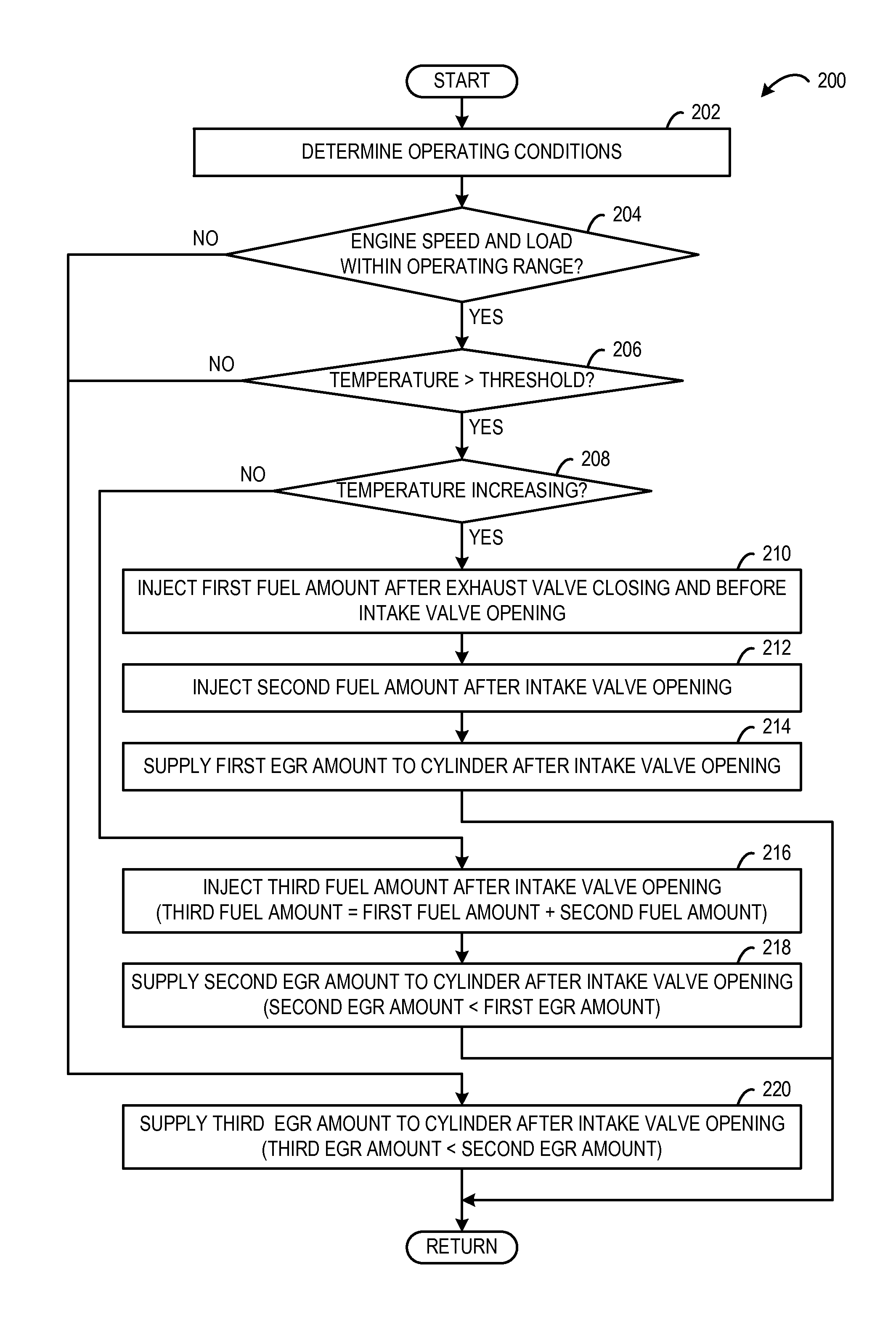
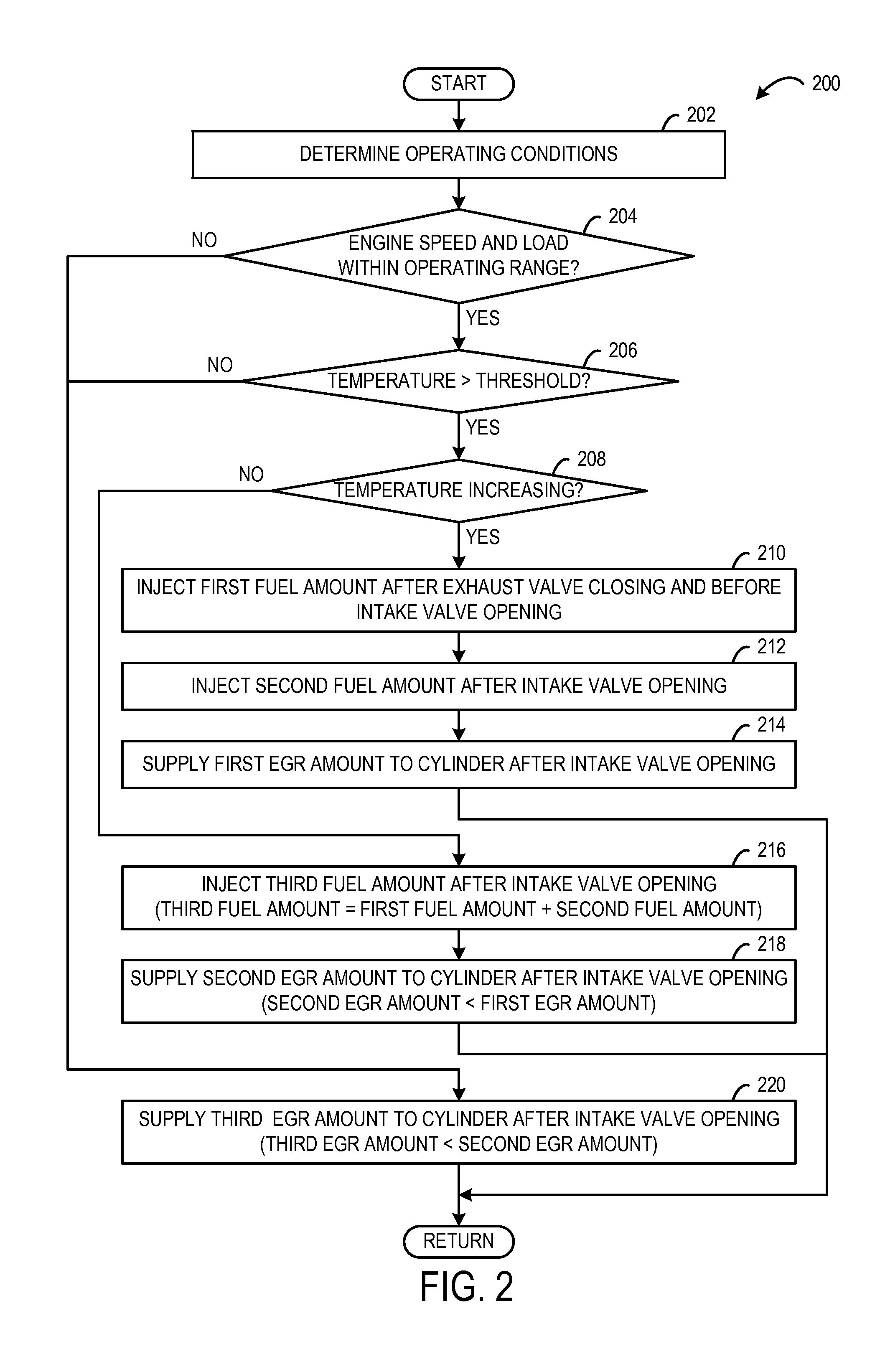
[0004]By injecting an amount of fuel after exhaust valve closing and before intake valve opening, the fuel may interact with the hot / warm conditions in the cylinder. Such interaction causes at least some of the fuel to be converted into chemical radicals. Those chemical radicals then act as a catalyst to enhance combustion during compression and combustion strokes. In other words, the additional chemical radicals created by fuel injection after exhaust valve closing and before intake valve opening, lower engine dilution to facilitate stable combustion with an increased amount of EGR relative to an approach where fuel is merely injected after intake valve opening. The increased EGR concentration may lower the engine temperature to reduce emissions and increase efficiency and engine knock resistance.

Problems solved by technology

However, the inventors herein have identified a potential issue with such an approach.
For example, the amount of EGR provided to the engine cylinders may be limited by an engine dilution limit where combustion stability becomes degraded.

Method used


Image

  • Approach for controlling exhaust gas recirculation
  • Approach for controlling exhaust gas recirculation
  • Approach for controlling exhaust gas recirculation

Examples


Embodiment Construction

[0016]The present description is related to controlling an engine to operate with a higher EGR concentration while maintain combustion stability, under some conditions. In particular, the approach includes injecting a small amount of fuel near the time of exhaust valve closing and before intake valve opening in what may be referred to as negative valve overlap followed by injection a second larger amount for combustion. When the first injected fuel amount mixes with residual exhaust gas in the hot cylinder, at least some of the fuel is converted into chemical radicals that act as a catalyst for combustion during the following combustion cycle. In other words, the chemical radicals created by the initial injection during negative valve overlap facilitate stable combustion even as an EGR concentration in the cylinder is increased. In one example, this control approach may be applied to a direct-injection, spark-ignition engine including an EGR system as shown in FIG. 1. However, the p...


PUM


Abstract

Various embodiments related to controlling EGR in an engine are disclosed. In one embodiment, a first EGR amount is supplied to a cylinder at a first temperature and a first engine speed and load. Further, at the first engine speed and load, as engine temperature increases from the first temperature to a second temperature, a first fuel amount is injected after exhaust valve closing and before intake valve opening while a second EGR amount is supplied to the cylinder that is greater than the first EGR amount.

Description

BACKGROUND AND SUMMARY[0001]Engines may be configured with exhaust gas recirculation (EGR) systems to divert at least some exhaust gas from an engine exhaust passage to an engine intake passage. By controlling EGR to provide a desired engine dilution, engine pumping work, engine knock, as well as NOx emissions may be reduced. For example, at partial throttle operating conditions, providing EGR to the cylinders of the engine allows for the throttle to be opened to a greater extent for the same engine load. By reducing throttling of the engine, pumping losses may be reduced, thus improving fuel efficiency. Further, by providing EGR to the engine, combustion temperatures may be reduced (especially in implementations where EGR is cooled prior to being provided to the cylinders). Cooler combustion temperatures provide engine knock resistance, and thus increase engine thermal efficiency. Further still, EGR reduces a combustion flame temperature that reduces an amount of NOx generated duri...

Claims


Application Information

Patent Timeline
Patent Type & Authority Patents(United States)
IPC IPC(8): F02M25/07F02D41/30F02D41/00F02D21/08F02D13/02F02D43/00F02B75/12
CPCF02D21/08F02D13/0207F02D13/0219F02D41/0057F02D41/3011F02B2075/125F02D13/0265F02D43/00Y02T10/123Y02T10/18Y02T10/47Y02T10/12Y02T10/40
Inventor YI, JIANWEN JAMESWOOLDRIDGE, STEVENVANDERWEGE, BRAD ALANYANG, SHIYOUMCCARTHY, THOMAS A.
Owner FORD GLOBAL TECH LLC
Learn More