
Anchoring systems for drilling tools

a technology for anchoring systems and drilling tools, which is applied in the direction of drilling pipes, drilling rods, and well accessories, etc., can solve the problems of inability to provide wob, inability to use flexible cables, and inability to compress coiled tubing. to achieve the effect of increasing or decreasing the anchoring for

Inactive Publication Date: 2015-11-03
SCHLUMBERGER TECH CORP
View PDF31 Cites 2 Cited by
  • Summary
  • Abstract
  • Description
  • Claims
  • Application Information

AI Technical Summary

Benefits of technology

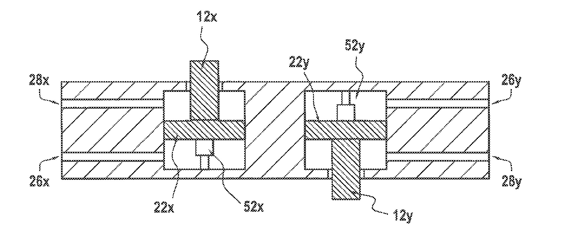
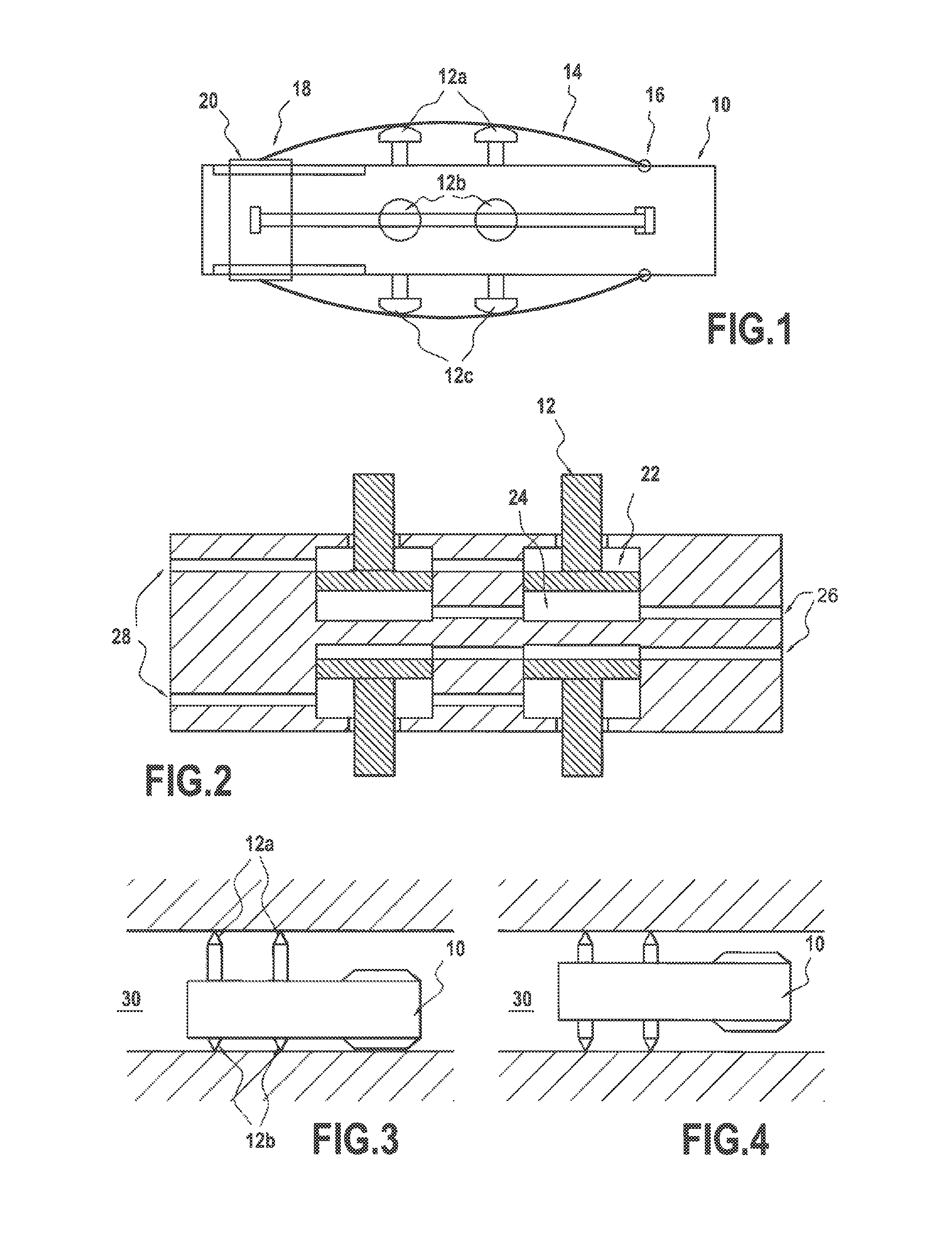
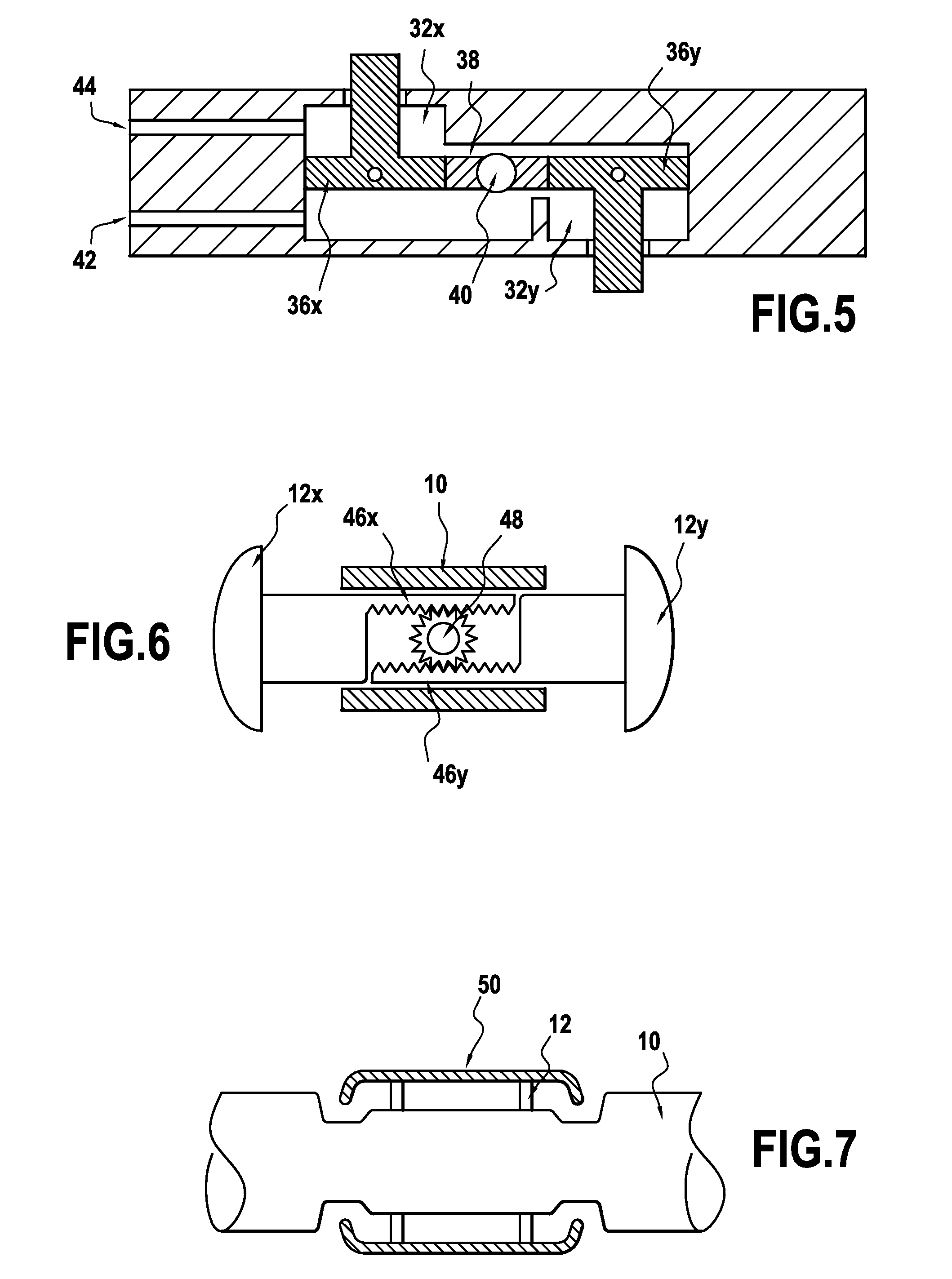
[0022]Preferably, the anchoring portion comprises a one-way locking member arranged such that axial movement of the tool body in one direction in the borehole increases the anchoring force and in the opposite direction decreases the anchoring force. The one way locking member can comprise an anchor plate which is mounted on the anchoring member by means of pegs engaging in angled slots such that, when deployed, movement of the tool causes the pegs to move in the slots to increase or decrease the anchoring force.

Problems solved by technology

However, problems can occur as the coiled tubing does not have great strength in compression.
Clearly a flexible cable cannot be used to provide WOB.
When drilling wells using a wireline drilling system, the tractor may encounter many situations where a classic piston anchoring system will not be adequate.
In cased-hole, during trips; the tractor can encounter obstructions from completion equipment, and weak tubing.

Method used


Image

  • Anchoring systems for drilling tools
  • Anchoring systems for drilling tools
  • Anchoring systems for drilling tools

Examples


Embodiment Construction

[0036]Drilling boreholes using a system such as that described in GB2398308 that has a wireline cable extending from the bottom-hole drilling assembly (BHA) to the surface offers many benefits in terms of reduction of cost-of-drilling, and reduction of assets and personnel on location. However, with these comes a reduction in the available power available to drill with. Wireline drilling tools of the type to which this invention particularly applies may have operational requirements to be able to kick-off from a parent well and turn at a very aggressive turn rate (up to 120° / 100 ft, or a 15 m radius), and then steer using very small doglegs to target depth. Since the conditions under which the tool must advance can vary considerably (small tubing, large casing, or open hole), various anchoring mechanisms may be required.

[0037]The invention provides techniques that address multiple issues that may be encountered when drilling a lateral hole. Some of these are general (standard and wi...


PUM


Abstract

An anchoring system for a tool in a borehole is provided. The anchoring system comprising a tool body, anchoring members which are operable to extend from the tool body so as to deploy an anchor portion into contact with the borehole wall such that when deployed. The anchoring members act to support the tool body in a central region of the borehole. Moreover, the anchoring members are connected to an operating mechanism which links deployment of the anchoring members so as to distribute the anchoring force and position of the anchoring members in a controlled manner.

Description

CROSS-REFERENCE TO RELATED APPLICATIONS[0001]The present application is based on and claims priority to GB Application No. 0722441.3, filed 15 Nov. 2007; and International Patent Application No. PCT / EP2008 / 009608, filed 6 Nov. 2008. The entire contents of each are herein incorporated by reference.TECHNICAL FIELD[0002]This invention relates to anchoring systems for use with drilling tools. In particular, the invention relates to anchoring systems for use with drilling tools that cannot rely on drill pipe for weight on bit and which generate rotation downhole.BACKGROUND ART[0003]In a conventional drilling setup, a drill bit is mounted on a bottom hole assembly (BHA) that is connected to a drill string made up of tubular members connected in an end-to-end arrangement. The BHA can include measuring instruments, a drilling motor, telemetry systems and generators. Penetration is achieved by rotating the drill bit while applying weight on bit (WOB). Rotation can be achieved by rotating the...

Claims


Application Information

Patent Timeline
Patent Type & Authority Patents(United States)
IPC IPC(8): E21B4/18E21B23/01E21B23/04E21B23/00
CPCE21B4/18E21B23/01E21B23/04E21B2023/008E21B23/001E21B23/04115E21B17/1014
Inventor KOTSONIS, SPYROLAVRUT, ERIC
Owner SCHLUMBERGER TECH CORP
Learn More