Method and apparatus for moulding cannulae

a technology of polymeric cannulae and injection moulding, which is applied in the field of manufacturing cannulae, can solve the problems of incomplete articles, unsuitable formed articles for intended use, and insufficient liquid interior portion of working fluid, and achieve the effect of improving the reliability and consistency of cannula

Inactive Publication Date: 2015-11-03
SSB TECH
View PDF6 Cites 0 Cited by
  • Summary
  • Abstract
  • Description
  • Claims
  • Application Information

AI Technical Summary

Benefits of technology

[0028]It is an object of the present invention to provide apparatus and methods to improve the reliability and consistency of cannulae produced from a mould used for the production of many cannulae from a single cycle of fluid-assisted injection moulding.

Problems solved by technology

On the one hand, injecting too little volume of liquid polymer, for example, can result in an incomplete article.
On the other hand, injecting too much volume of liquid polymer may lead to the working fluid not displacing enough of the liquid interior portion of the polymer to form a continuous conduit in the cannula.
In either example, the formed article may be unsuitable for its intended use and must be discarded because it does not meet performance specifications, particularly in medical applications.
This method is not suitable for multiple channels in a mould.
If there are many cavities in a mould the sudden rush of pressurised working fluid out of the polymer can destroy the cannulae at the worst, or result in a large proportion of defective cannulae.
This method could result in mechanical damage to surfaces of the cannulae, the damage being observable under microscopic observation.
Such damage could cause contamination if loose microscopic material was accidentally delivered to a subject or collected from a fluid source.
Such tight tolerances in the amount of liquid polymer delivered using the current methods means that it is difficult to achieve the desired product consistency.

Method used


Image

  • Method and apparatus for moulding cannulae
  • Method and apparatus for moulding cannulae
  • Method and apparatus for moulding cannulae

Examples


Embodiment Construction

[0032]The objects of the invention are best understood with reference to the embodiments described herein and with reference to the figures. It will be understood by those skilled in the art that the invention is not limited to the embodiments shown in the figures but includes embodiments not illustrated but within the scope of the claims appended hereto.

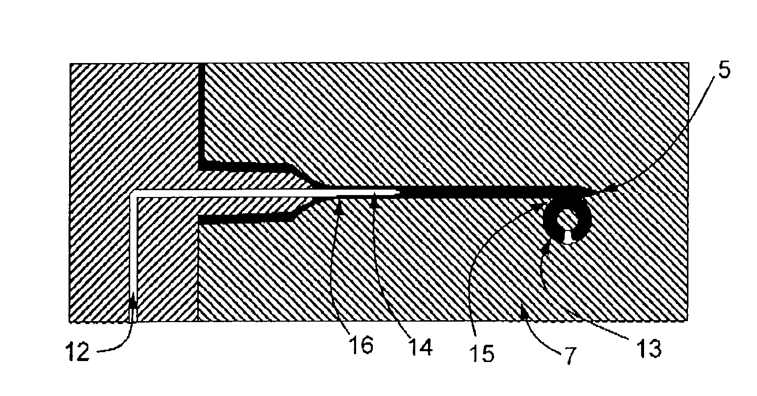
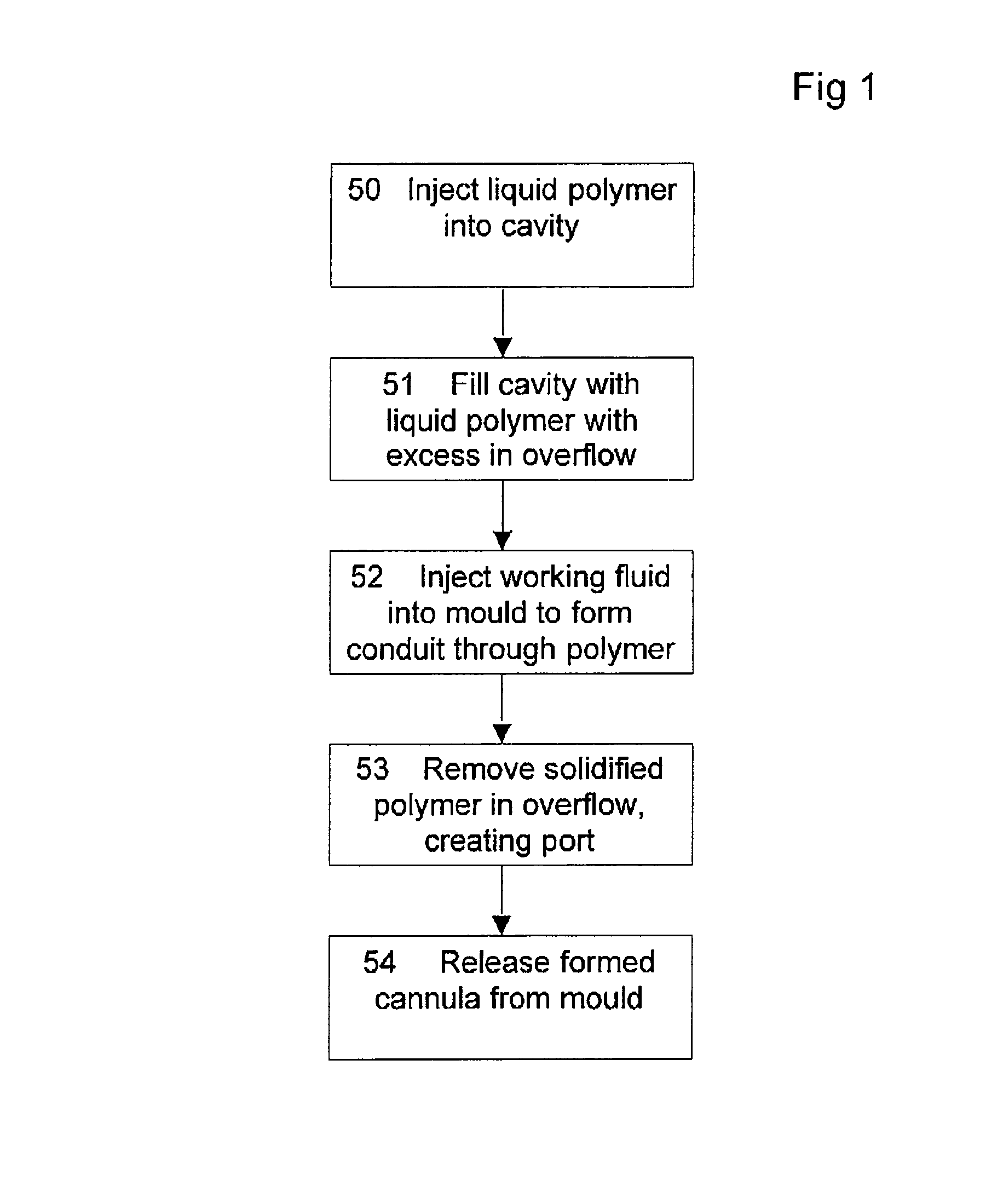
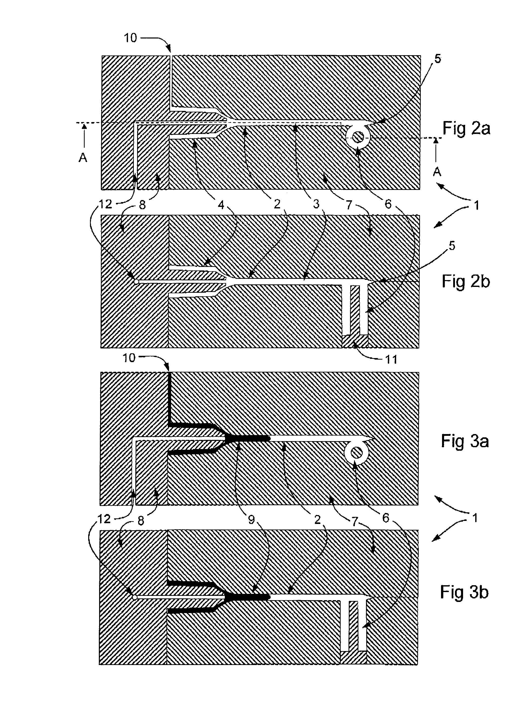
[0033]FIG. 1 is a schematic diagram illustrating the method of the invention. FIGS. 2 to 8 show one embodiment of the method and with suitable apparatus to practice the method. FIGS. 9 and 10 show alternative embodiments within the scope of the invention. FIG. 1 shows generally the steps comprising one aspect of the injection in which an article such as a cannula having a lumen therethrough is formed by fluid-assisted injection moulding. In a first step 50 an appropriate amount of liquid polymer is injected into at least one cavity in a mould which is ready to receive the liquid polymer. In a second step the at least one cavity is f...


PUM

PropertyMeasurementUnit
volumeaaaaaaaaaa
mechanicalaaaaaaaaaa
shapeaaaaaaaaaa

Abstract

The present invention provides apparatus and methods for injection molding polymeric cannulae from liquid polymeric materials. The method includes injecting pressurized liquid polymer into a mold cavity and into an overflow and forming a conduit by forcing pressurized working fluid through the solidifying liquid polymer into the overflow. The invention provides a mold for fluid-assisted injection molding articles from polymeric materials, the mold comprising at least two parts defining a cavity having a conduit portion incorporating a needle portion; a channel for liquid polymer ingress; a channel for pressurized fluid ingress; and an overflow in communication with the conduit portion. The mold may incorporate a plurality of cavities. Preferably the volume of the overflow is equal to or greater than the volume of the conduit portion. Preferably the mold incorporates a separating means for separating the overflow from a cannula portion of an article formed in the mold.

Description

CROSS REFERENCE TO RELATED APPLICATIONS[0001]This application is a National Stage of International Application No. PCT / AU2008 / 000296, filed Mar. 6, 2008, claiming priority to Australian Patent Application No. 2007901163, filed Mar. 7, 2007, the contents of both applications being incorporated herein by reference in their entirety.FIELD OF INVENTION[0002]This invention relates to the field of manufacturing cannulae, in particular polymeric cannulae, and more particularly, methods and apparatus for fluid-assisted injection moulding of polymeric cannulae.BACKGROUND TO THE INVENTION[0003]It is known in the art that a cannula for use, particularly a single use, of transferring fluid into or from objects, in particular living beings, can be moulded from polymeric materials. Stevens, Smith and Bartlett described a method for manufacturing hypodermic needles in U.S. Pat. No. 5,620,639, hereinafter referred to as the '639 patent, which is incorporated herein by reference. The method disclose...

Claims


Application Information

Patent Timeline
Patent Type & Authority Patents(United States)
IPC IPC(8): B29C49/06A61M25/00A61M5/158B29C45/17B29L31/00
CPCB29C45/1711A61M5/158A61M25/0009B29C2045/1719B29C2045/1724B29C2045/1728B29L2031/7542B29L2031/7544
Inventor SMITH, TREVOR
Owner SSB TECH
Why Eureka
Try Eureka