Rear lock-up rimfire bolt action assembly

a bolt action and rear lock technology, applied in the direction of breech mechanism, weapon components, etc., can solve the problems of vibration affecting the trajectory of bullets, affecting accuracy, and the bolt mechanism is subject to enormous stress

Active Publication Date: 2015-10-20
DIORIO ANTHONY JOSEPH
View PDF20 Cites 8 Cited by
  • Summary
  • Abstract
  • Description
  • Claims
  • Application Information

AI Technical Summary

Benefits of technology

[0010]The present teachings also provide a rear lock-up bolt action assembly including a receiver body having a lug groove formed in the vicinity of a rear portion of the receiver body. The lug groove defines a rear shoulder surface. The rear lock-up bolt action assembly further includes a bolt assembly including a bolt handle and at least three rear locking lugs arranged on a rear portion of the bolt assembly. Each of the at least three rear locking lugs defines a rear seating surface. The bolt assembly is configured to be supported in the receiver body such that when a round is fired the rear seating surfaces of each of the three rear locking lugs are forced to mate with the rear shoulder surface of the lug groove thereby evenly distributing a bolt pressure.
[0011]The present teachings still further provide a rear lock-up rimfire bolt action assembly including a receiver body including a lug groove formed in the vicinity of a rear portion of the receiver body. The rear lock-up rimfire bolt action assembly further includes a bolt assembly including an offset firing pin, a bolt handle, and at least three rear locking lugs arranged on a rear portion of the bolt assembly. The bolt assembly is configured to be supported in the receiver body such that when a rimfire cartridge is fired, the three rear locking lugs are forced to mate with the lug groove thereby evenly distributing a bolt pressure on the receiver body.

Problems solved by technology

Moreover, due to the nature of high-powered rifles, the bolt mechanism is subjected to enormous stress as gas pressure caused by cartridge firing rapidly builds and expels the projectile from the barrel.
The resulting lag time in the barrel exposes the bullet to vibrations created during the firing process and these vibrations affect the bullet's trajectory.
It has been proven through extensive testing that a front lock-up bolt design generally used with center fire ammunition accentuates the vibrations experienced by rimfire cartridges due to the close proximity of the lugs to the case rim and the lag time, and is therefore considered detrimental to accuracy.
This results in the bolt assembly flexing and moving during the firing of a round.
Such movement of the bolt assembly also prevents consistent positioning of the components of the bolt action thereby jeopardizing accurate, repeatable performance by the shooting competitor.
Accordingly, there exists a need for a rear lock-up rimfire bolt action assembly that can evenly distribute the forward pressure the bolt assembly places on a chambered round and will not allow the bolt assembly to move or flex within the action body during the firing of the round.

Method used


Image

  • Rear lock-up rimfire bolt action assembly
  • Rear lock-up rimfire bolt action assembly
  • Rear lock-up rimfire bolt action assembly

Examples


Embodiment Construction

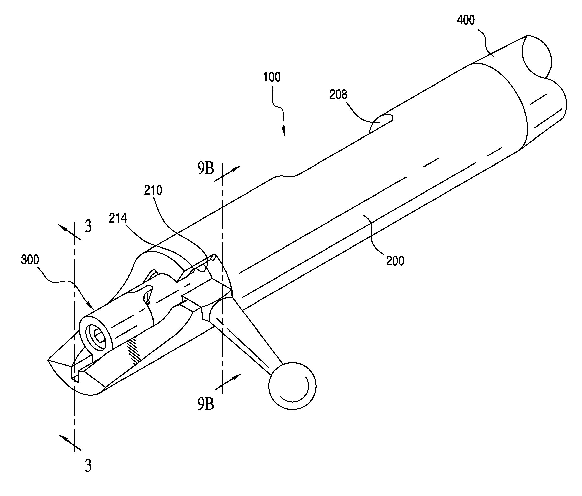
[0025]Referring to FIGS. 1-3, a bolt action assembly 100 of the present teachings which is capable of being mounted onto a stock of a firearm is shown. The bolt action assembly 100 includes a receiver body 200 and a bolt assembly 300 that is adapted to be received within the receiver body 200. The receiver body 200 has a front aperture 202 that is concentric with and capable of being in communication with a barrel 400 of a firearm. The receiver body 200 has a rear aperture 204 through which bolt assembly 300 can be inserted and secured to the receiver body 200 in a cocked and uncocked position. The apertures 202, 204 are connected by a central bore 206 within receiver body 200. The receiver body 200 can include a loading port 208 into which a cartridge (not shown) can be inserted for loading into the breech of the firearm barrel (also not shown).

[0026]As will be discussed in more detail below, the receiver body 200 further includes a lug groove 210 that is located in the vicinity of...


PUM


Abstract

A rear lock-up bolt action assembly is provided. The bolt action assembly can include a receiver body including a front aperture capable of receiving a firearm barrel and a rear aperture. A lug groove can be formed in the vicinity of the rear aperture of the receiver body. The bolt action assembly can also include a bolt assembly including a bolt handle and three rear locking lugs arranged on a rear portion of the bolt assembly. The bolt assembly is configured to be arranged in the receiver body such that the three rear locking lugs are capable of being rotated within the lug groove when the bolt handle is rotated. When a round is fired, the three rear locking lugs are forced to mate with the lug groove thereby evenly distributing a bolt pressure on the receiver body.

Description

CROSS REFERENCE TO RELATED APPLICATION[0001]The present application claims the benefit from earlier filed U.S. Provisional Patent Application No. 61 / 973,774, filed Apr. 1, 2014, which is incorporated herein in its entirety by reference.FIELD OF THE INVENTION[0002]The present teachings relate to a bolt action system for a firearm. In particular, the present teachings relate to a rimfire bolt action that can facilitate the precise positioning of the bolt and firing pin within the receiver in order to improve accuracy and ease of use of the firearm.BACKGROUND OF THE INVENTION[0003]There are a variety of known designs of bolt actions for rifles. A design objective of bolt actions is the precise alignment of a bolt face to a cartridge chamber to properly position the firing pin to strike the primer of a cartridge. To achieve precise and repeatable firing results during competition shooting, it is desirable to accurately secure the bolt mechanism in its proper position and keep it relativ...

Claims


Application Information

Patent Timeline
Patent Type & Authority Patents(United States)
IPC IPC(8): F41A3/00F41A3/32F41A3/66
CPCF41A3/32F41A3/66F41A3/24
Inventor DIORIO, ANTHONY JOSEPH
Owner DIORIO ANTHONY JOSEPH
Why Eureka
Try Eureka