
Chair assembly

a technology for chairs and parts, applied in the field of chairs, can solve the problems of high manufacturing cost, harmed outer appearance by the screws fastening the parts, complicated assembly and time-consuming, etc., and achieve the effects of reducing manufacturing and transportation costs, improving outer appearance, and reducing manufacturing costs

Active Publication Date: 2015-10-20
HUANG TSUNG CHIEH
View PDF19 Cites 23 Cited by
  • Summary
  • Abstract
  • Description
  • Claims
  • Application Information

AI Technical Summary

Benefits of technology

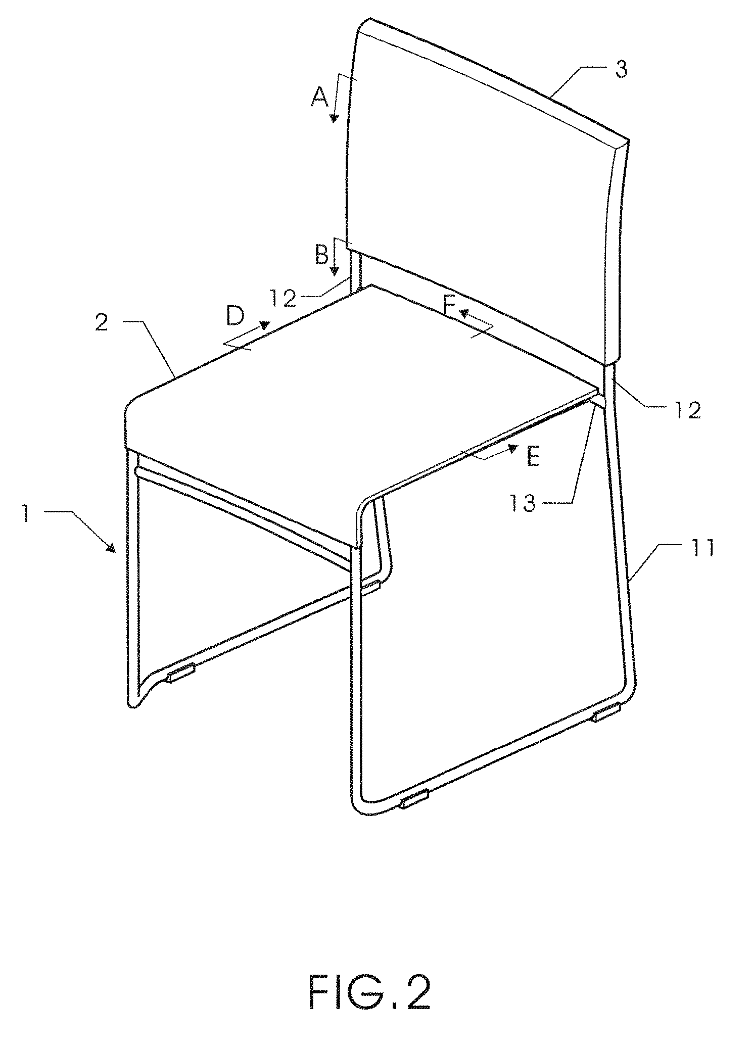
The present invention provides a chair assembly that is cost-effective and easy to assemble. The chair has a frame with two foot frames and two back supports. The frame has a transverse shaft linking the two foot frames and an assembling sheet. The seat has cuts for receiving the foot frame and the transverse shaft, and the back has cuts for receiving the back supports. The seat and back are fixed to the frame through the assembling sheet with fastening components. The chair has a tidy appearance without any visible fastening between parts. The technical effects of the invention are lower manufacturing and transportation costs, as well as improved outer appearance.

Problems solved by technology

Such assembly is complicated and time-consuming with higher manufacture cost.
An outer appearance will be harmed by the screws fastening the parts of the chair.

Method used


Image

  • Chair assembly
  • Chair assembly
  • Chair assembly

Examples


first embodiment

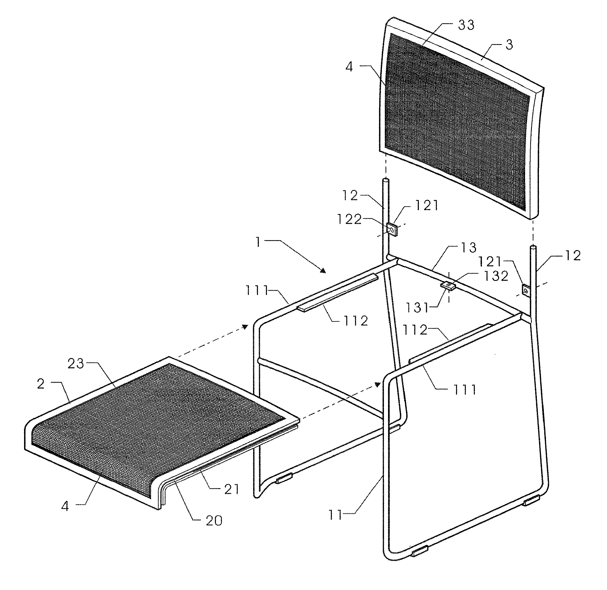
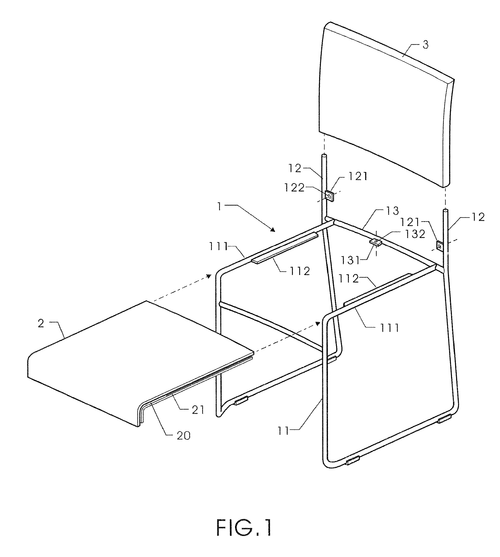
[0029]Referring to FIGS. 1 to 16, the first embodiment includes a frame 1, seat 2, and back 3. The frame 1 includes two linked foot frames 11 for holding the seat 2 and a back support 12 for assembling the back 3. An upper rod 111 of the foot frame 11 has an extending supporting rib 112 for holding the seat 2. The back support 12 extending from the frame 1 has an assembling sheet 121 for assembling the back 3, the assembling sheet 121 has a through hole 122. A transverse shaft 13 linking the two foot frames on the rear of the frame 1 has a assembling sheet 131, the assembling sheet 131 has a through hole 132.

[0030]Referring to FIGS. 8 to 16, the seat 2 has a cut 20 for receiving the upper rod 111 of the foot frame 11 on two sides of the seat 2 as shown in FIGS. 12, 14, and 15. A slot 21 is formed to the cut 20 for receiving the supporting rib 112. The rear side of the seat 2 also has a cut 20 for receiving the transverse shaft 13 as shown in FIGS. 11, 13, and 16, and a positioning s...

second embodiment

[0032]Referring to FIGS. 17 to 20, the present invention is illustrated. The embodiment includes a frame 1, seat 2, back 3, and net cloth 4 arranged to the seat 2 and back 3. The seat 2 is a frame having a central cut as shown in FIG. 20, and the back 3 is also a frame having a central cut as shown in FIG. 19. A groove 23 enclosing the central cut of the seat 2 is formed to an upper surface of the seat 2 for fastening edges of the net cloth 4 so that the net cloth 4 will cover the central cut of the seat 2. A groove 33 enclosing the central cut of the back 3 is formed to a front side of the back 3 for fastening edges of the net cloth 4 so that the net cloth 4 will cover the central cut of the back 3.

[0033]Referring to FIGS. 19 and 20, the edges of the net cloth 4 are wrapped around a rectangle flexible positioning frame 6 from an outer rim of the frame 6. The cross-section of the positioning frame 6 is rectangular. The edges of the net cloth 4 are wrapped and fixed to the positionin...


PUM


Abstract

A chair assembly includes a frame, seat, and a back. The frame has two foot frames and two back supports. The foot frame has an upper rod, and an extending supporting rib is formed to the upper rod. The back support has an assembling sheet. The seat has a cut for receiving the upper rod of the foot frame on two lateral sides thereof, and the rear side of the seat also has a cut for receiving the transverse shaft of the frame. The back has two pin holes on two lateral sides of the bottom thereof for receiving the back supports of the frame, and the pin hole has a slot for receiving the assembling sheet of the back support. The seat is fixed to the frame, and the back is fixed to the frame through the assembling sheet of the back support with two fastening components.

Description

FIELD OF THE INVENTION[0001]The present invention relates to chairs, and particular to a chair assembly accomplished the assembling between a seat and a frame with one fastening component and the assembling between a back and the frame with two fastening components. The chair assembly has a nice and tidy appearance without seeing the fastening between the parts.DESCRIPTION OF THE PRIOR ART[0002]Chairs usually consist of a frame, seat, and back. There are many types of chair such as wooden chair with wooden seat and back, wooden chair with cushion seat and back, metal chair with metal seat and back, or metal chair with cushion seat and back.[0003]Conventional assembly of chair usually uses a lot of screws to assemble the seat and back to the frame. Such assembly is complicated and time-consuming with higher manufacture cost. An outer appearance will be harmed by the screws fastening the parts of the chair.[0004]Therefore, for the purpose of reduce the cost of manufacture and transpor...

Claims


Application Information

Patent Timeline
Patent Type & Authority Patents(United States)
IPC IPC(8): A47C3/04A47C5/06A47C5/10A47C4/02A47C7/28
CPCA47C4/02A47C3/04A47C5/06A47C5/10A47C7/282
Inventor HUANG, TSUNG-CHIEH
Owner HUANG TSUNG CHIEH
Learn More